
Cement Retarder Systems, and Retarded Cement Compositions

a technology of cement retarder and composition, which is applied in the direction of sealing/packing, chemistry apparatus and processes, and wellbore/well accessories. it can solve the problems of difficult use of cement retarder systems and problems in effective placement of cement slurry

Inactive Publication Date: 2007-10-11
SCHLUMBERGER TECH CORP
View PDF8 Cites 50 Cited by
  • Summary
  • Abstract
  • Description
  • Claims
  • Application Information

AI Technical Summary

Problems solved by technology

This can lead to problems in effective placement of the cement slurry.
The time taken to pump a cement slurry into a deep well can mean that the onset of thickening caused by cement setting can become a problem, potentially leading to setting of the cement before it is properly placed either around the casing or as a plug.
However, these systems have been found difficult to use at temperatures of 250° C.

Method used


Image

  • Cement Retarder Systems, and Retarded Cement Compositions
  • Cement Retarder Systems, and Retarded Cement Compositions

Examples


Embodiment Construction

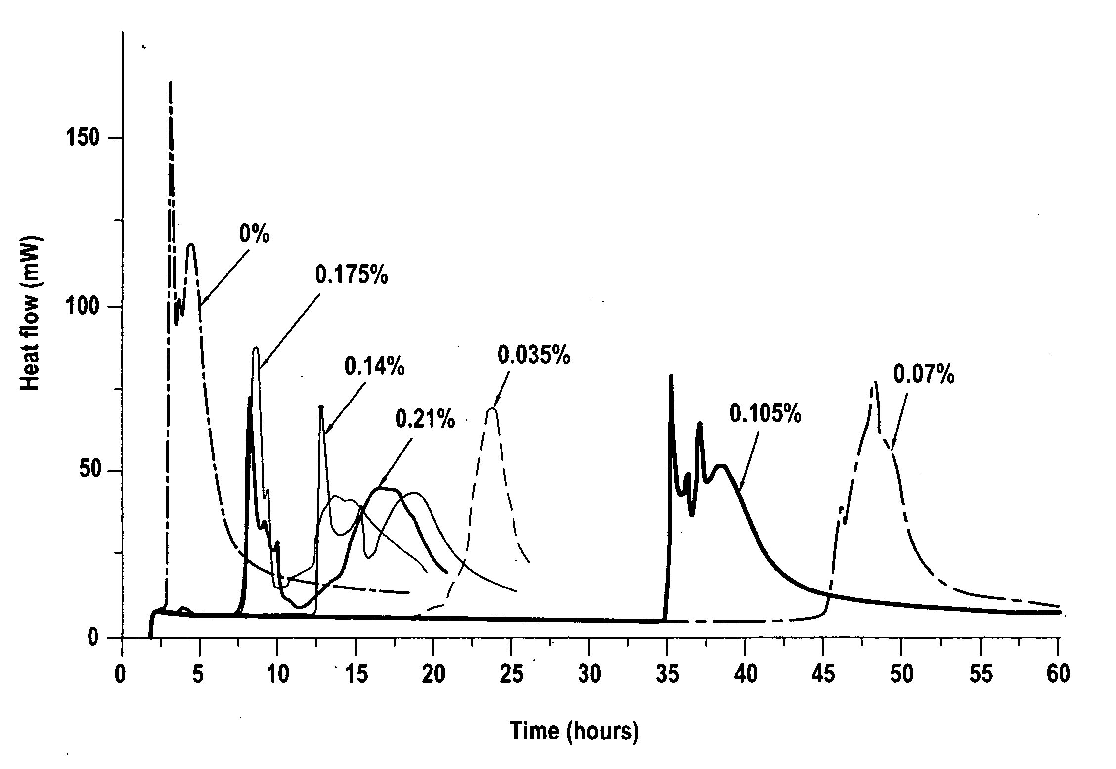
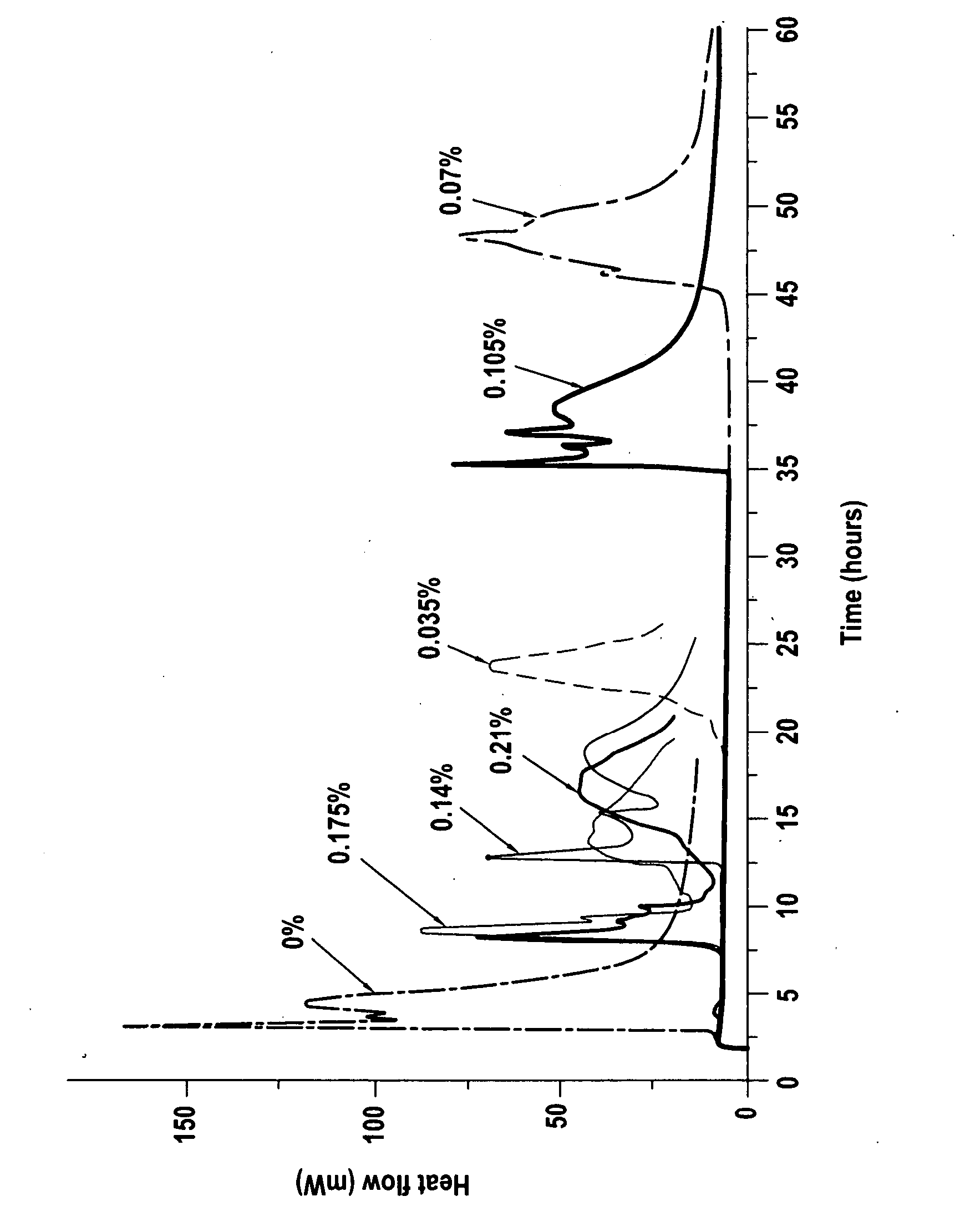
[0025]FIG. 1 shows a plot of heat flow vs. time for a series of cement compositions measured in an isothermal calorimeter to determine the length of the induction period (time period during which the cement slurry does not set), the end of the induction period being indicated by the sudden increase in heat flow. The concentration of borate was maintained constant at 4% BWOC (by weight of cement) in all tests plotted in FIG. 1, and the concentration of EDTMP was varied between 0% and 0.21%, as indicated. FIG. 1 shows that the length of induction period varies with the borate:EDTMP ratio.

[0026] At 0% EDTMP the cement begins to set as soon as the test temperature is reached, (i.e., 182° C. [360° F.]), after about 2 and a half hours. The addition of very small concentrations of EDTMP (0.035 and 0.07% BWOC) significantly lengthens the induction period to 20 and 45 hours, respectively. Further additions of EDTMP lengthen the induction period by a lesser amount, 7 and a half hours with 0....


PUM

PropertyMeasurementUnit
Temperatureaaaaaaaaaa
Fractionaaaaaaaaaa

Abstract

A cement retarder system for use in underground wells included a borate compound, an organophosphonate salt, and a copolymer formed from AMPS and a monomer selected from the group consisting of acrylic acid, acrylamide and mixtures thereof. A method of using the retarder system in an underground well having a borehole drilled therein with a borehole wall, and further including a casing disposed in said borehole, such that an annulus exists between said casing and said borehole wall, comprising the steps of providing a cement composition and a liquid carrier, providing a retarder system for said cement composition comprising a borate compound, an organophosphonate salt, and a copolymer formed from AMPS and a monomer selected from the group consisting of acrylic acid, acrylamide, and mixtures thereof, mixing a sufficient amount of said retarder system to create a desired induction period with said cement composition and said liquid carrier to form a cement slurry, pumping the cement slurry from the surface down the casing, and causing said slurry to return to the surface in the annulus between the casing and the borehole wall.

Description

RELATED APPLICATION DATA [0001] This application claims the benefit of EP Patent Application 06290547.6 filed Mar. 31, 2006 entitled, “Cement Retarders” and also claims the benefit of U.S. Provisional Application 60 / 746,806 filed May 9, 2006 entitled “Cement Retarders”.FIELD OF THE INVENTION [0002] This invention relates to cement retarder systems and the retarded cement compositions produced by their use. In particular, the invention relates to such systems and compositions for use in cementing wells such as oil, gas and water wells. BACKGROUND OF THE INVENTION [0003] Cement slurries are used in the construction of wells such as oil and gas wells. One such use is in the setting of casing in the well. In this procedure, a casing (typically a steel tubular liner) is positioned in the well and a cement slurry is pumped from the surface down the casing so as to return to the surface in the annulus between the casing and the borehole wall. The cement fills the annulus and, once set, hol...

Claims


Application Information

Patent Timeline
IPC IPC(8): E21B33/13C04B24/26C04B24/24E21B33/14
CPCC04B28/02C04B40/0039C04B2103/22C09K8/467C04B22/0013C04B24/003C04B24/2652C04B24/163C04B24/2641
Inventor MICHAUX, MICHELPYATINA, TATIANA
Owner SCHLUMBERGER TECH CORP
Learn More