Temperature based clearance control for vehicle brake

Inactive Publication Date: 2007-10-11
ARVINMERITOR TECH
View PDF10 Cites 29 Cited by
  • Summary
  • Abstract
  • Description
  • Claims
  • Application Information

AI Technical Summary

Benefits of technology

[0005] An adjustment mechanism for a vehicle brake uses an electric motor to optimize brake clearance. A controller controls the electric motor to adjust brake clearance based on brake temperature and wheel speed. An increase in brake temperature during non-braking events signifies brake drag, and once brake drag is identified, the controller actuates the electric motor to increase brake clearance. The controller also adjusts brake clearance to accommodate for brake wear. During a specified adjustment cycle, when wheel speed is above a predetermined speed value, the controller actuates the electric motor to optimize brake clearance.
[0006] In one example, the vehicle brake assembly includes a set of pads that are engaged against a rotating brake rotor during a braking event. If drag is identified, the controller actuates the

Problems solved by technology

As brake pads wear, the brake clearance increases, which can adversely affect the capability of the vehicle brake to achieve maximum brake torque.
One disadvantage with this type of system

Method used


Image

  • Temperature based clearance control for vehicle brake
  • Temperature based clearance control for vehicle brake
  • Temperature based clearance control for vehicle brake

Examples


Embodiment Construction

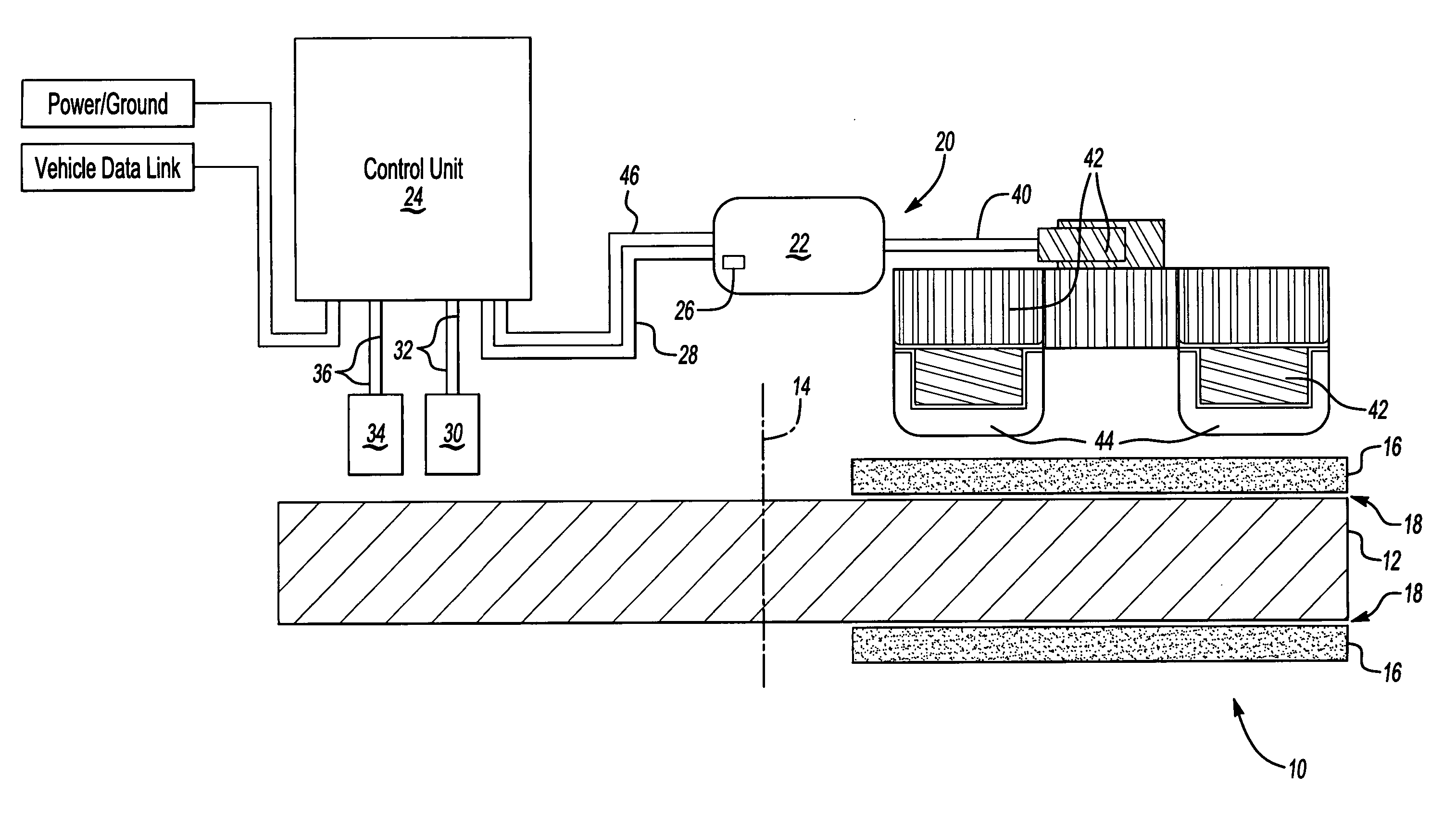
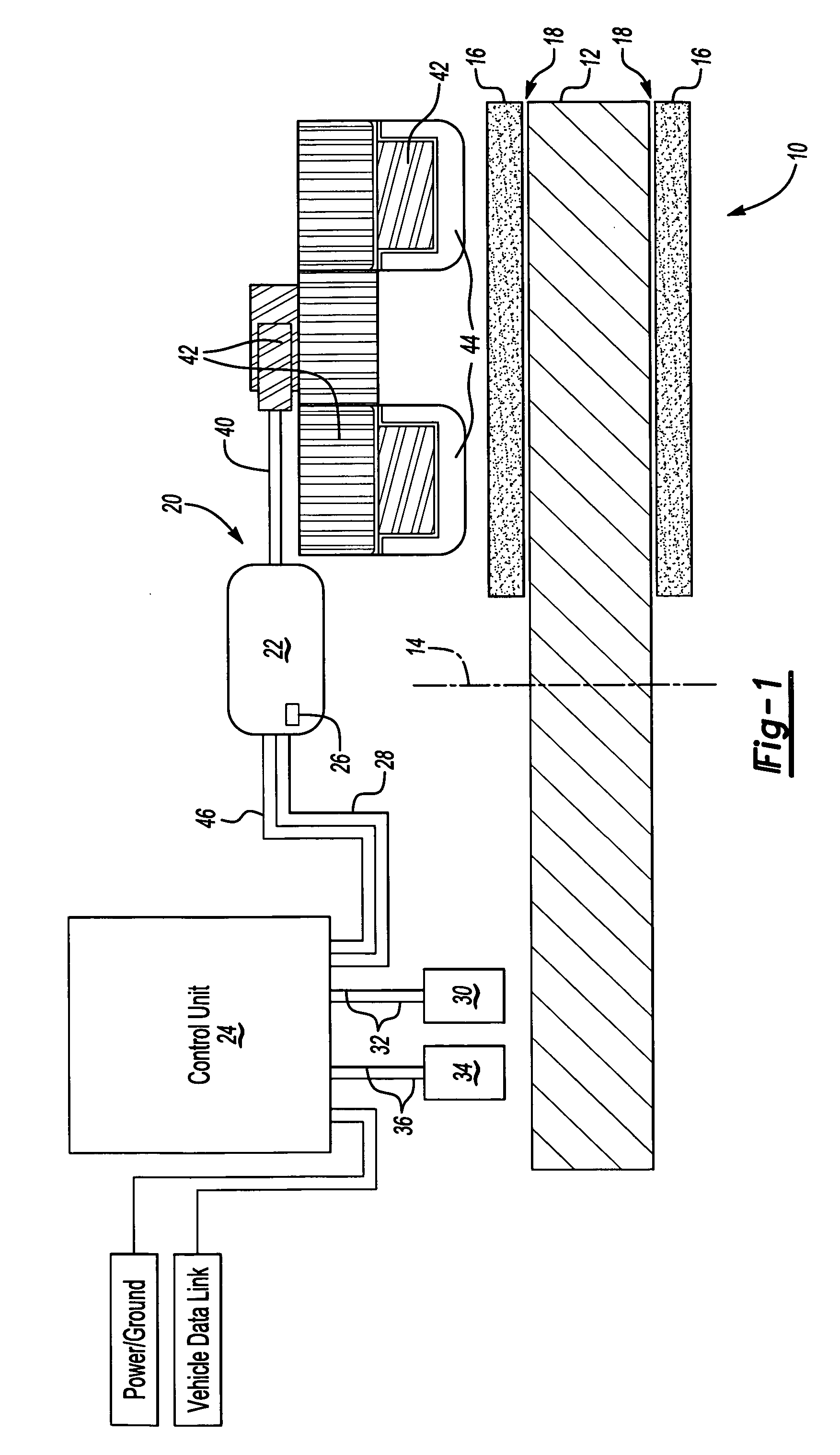
[0010] As shown in FIG. 1, a vehicle brake 10 includes a rotor 12 that rotates about an axis 14. Brake pads 16 are mounted to a non-rotating vehicle structure (not shown), and are spaced by a clearance shown generally at 18 from the rotor 12 when the vehicle brake 10 is not applied.

[0011] An adjustment mechanism 20 that operates according to the subject invention is used to optimize the clearance 18 to accommodate both pad wear and brake drag. While the vehicle brake 10 shown in FIG. 1 comprises a disc brake, it should be understood that the adjustment mechanism 20 and method of operating the adjustment mechanism 20 could also be used with other types of vehicle brakes.

[0012] The adjustment mechanism 20 includes an electric motor 22 that is operated by a control unit or controller 24. The controller 24 includes a power / ground connection interface and a vehicle data link, as indicated in FIG. 1. The electric motor includes a position sensor 26 that monitors motor position as known....


PUM


Abstract

An adjustment mechanism for a vehicle brake uses an electric motor to adjust brake clearance based on brake temperature and wheel speed. A temperature sensor transmits brake temperature data to a controller. If a brake is dragging during non-braking events, the controller identifies an increase in brake temperature and actuates the electric motor to increase brake clearance. The controller also adjusts brake clearance to accommodate for brake wear. When wheel speed is above a predetermined speed value, the controller actuates the electric motor to move a non-rotating brake component toward a rotating brake component until a predetermined temperature increase is sensed. Once the predetermined temperature increase is identified, the electric motor moves the non-rotating brake component away from the rotating brake component to provide an optimized brake clearance.

Description

TECHNICAL FIELD [0001] An adjustment mechanism for a vehicle brake utilizes an electric motor and controller to optimize brake clearance based on brake temperature and wheel speed. BACKGROUND OF THE INVENTION [0002] Vehicle brakes include adjustment mechanisms that adjust brake clearance, which comprises a distance between a brake pad and a rotating brake rotor when the vehicle brake is not applied. A minimum brake clearance is required such that brake pads do not drag against the brake rotor. As brake pads wear, the brake clearance increases, which can adversely affect the capability of the vehicle brake to achieve maximum brake torque. To compensate for this an adjustment mechanism is used to move the brake pads toward the brake rotor as the pad wears. [0003] One type of known adjustment mechanism utilizes a mechanical adjustment system that operates in a manner similar to that of a clutch with a known amount of backlash. One disadvantage with this type of system is that if over-a...

Claims


Application Information

Patent Timeline
IPC IPC(8): F16D55/02
CPCB60T17/221F16D2066/001F16D2065/386F16D65/568
Inventor CARON, LAVERNE A.
Owner ARVINMERITOR TECH
Why Eureka
Try Eureka