Opthalmologic Apparatus

a technology of opthalmologic and ophthalmologic tubes, which is applied in the field of ophthalmologic tubes, can solve the problems of imposing mental and physical strain on the subject, requiring time or labor, and utilizing ultrasonic waves

Active Publication Date: 2007-10-11
KK TOPCON
View PDF1 Cites 70 Cited by
  • Summary
  • Abstract
  • Description
  • Claims
  • Application Information

AI Technical Summary

Benefits of technology

[0056]FIG. 14 is a schematic diagram showing one example of the appearance of a conventional ophthalmic apparatus (optical image measuring device).
[0057]FIG. 15 is

Problems solved by technology

Methods of utilizing ultrasonic waves are problematic in that they impose mental and physical strain on the subject during measurement by bringing an ultrasonic probe into contact with the cornea of the eye (more specifically, by indirect contact via liquid or gel ultrasonic waves medium).
Moreover, since the eye needs to be disinfected prior to mea

Method used


Image

  • Opthalmologic Apparatus
  • Opthalmologic Apparatus
  • Opthalmologic Apparatus

Examples


modified example

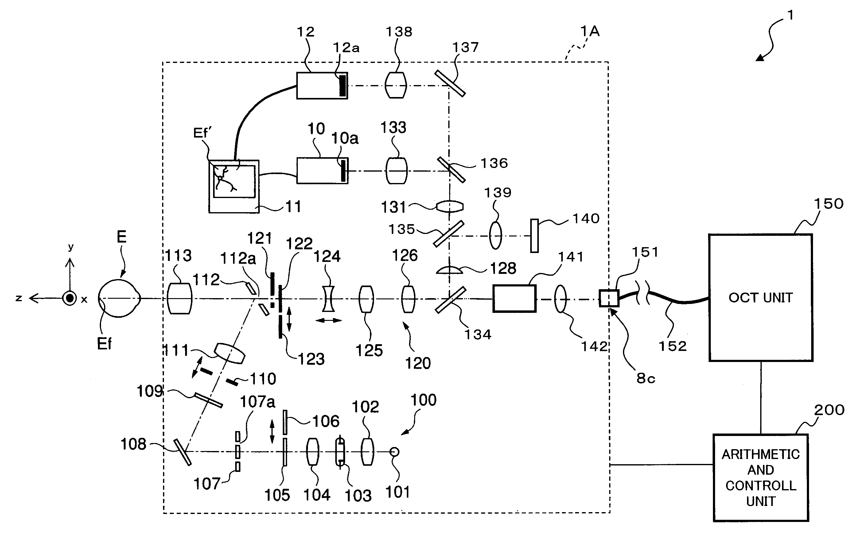
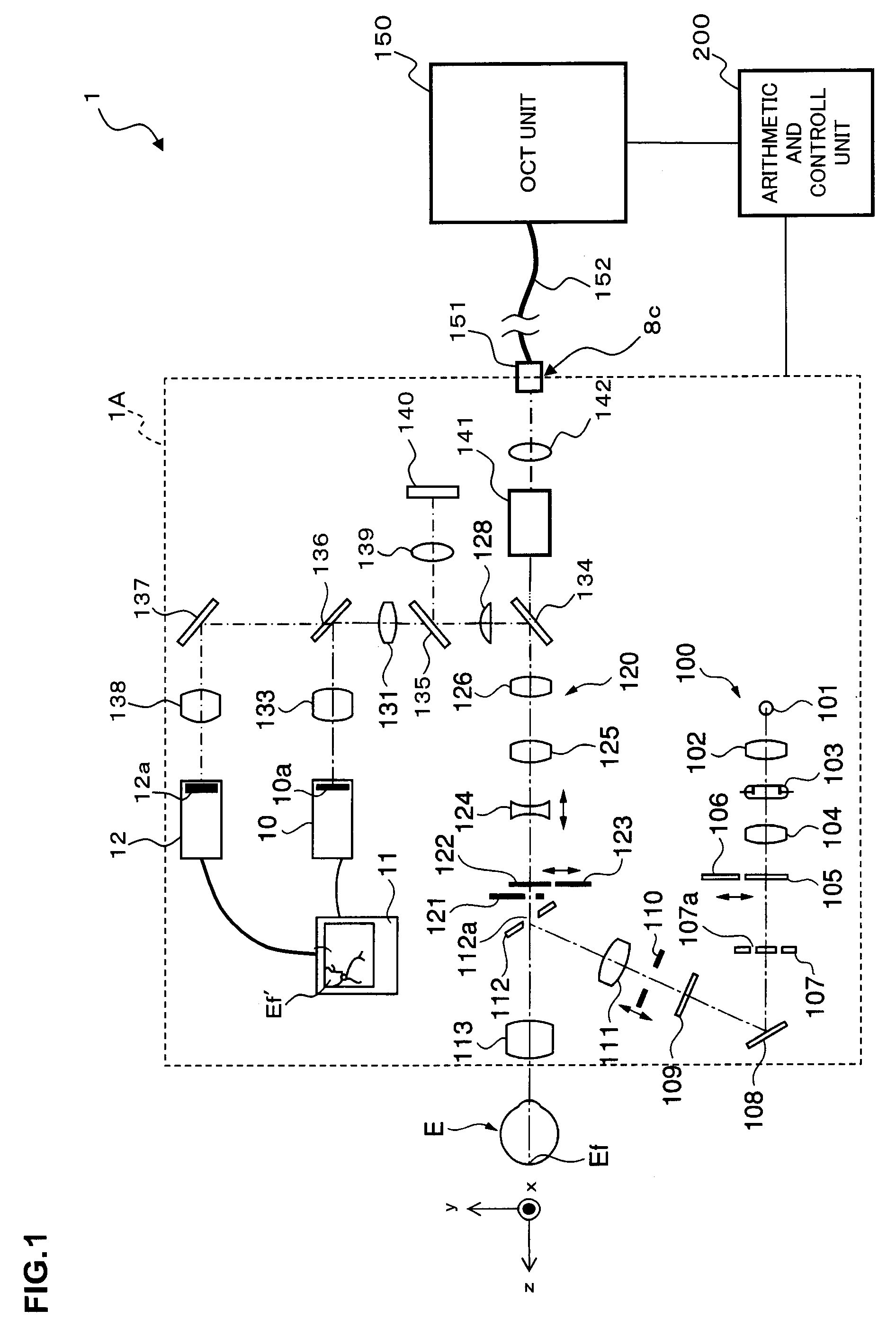
[0190]The configuration described above is merely one example to preferably implement the ophthalmic apparatus related to the present invention. Therefore, optional modifications may be implemented appropriately within the scope of the present invention.

[0191]In the above embodiment, the reference mirror 174 is arranged at a position corresponding to the surface of the fundus oculi Ef to determine the intraocular distance from the incident position of the signal light LS to the reflection point on the surface of fundus oculi Ef (such as axial length); however, the invention is not limited to such arrangement. For example, when arranging the reference mirror 174 at a position corresponding to a certain depth from the surface of the fundus oculi Ef, it is possible to determine the intraocular distance from the incident position of the signal light LS to the position corresponding to that certain depth by performing a process similar to that of the above embodiment.

[0192]FIG. 13 shows ...


PUM


Abstract

The ophthalmologic apparatus 1 splits low coherence light LO into a signal light LS and a reference light LR, the interference light LC being generated by having the signal light LS overlap with the reference light LR, and detects this interference light LC. In addition, the apparatus comprises an optical alignment system 190A for performing the alignment of an optical system forming the signal light path to the eye EL. An intraocular distance calculator 214 determines the distance between the position where the signal light LS has been introduced onto the eye E and the position where the signal light LS has been reflected by the fundus oculi E based on length of the optical path of the signal light, the length of the optical path of the reference signal light, the working distance after alignment, and the detection signal output by the CCD 184 (or signal intensity data).

Description

BACKGROUND OF THE INVENTION [0001]1. Field of the Invention[0002]The present invention relates to an ophthalmologic apparatus capable of measuring distance in the oculus of an eye.[0003]2. Description of the Related Art[0004]For an ophthalmologic apparatus for measuring distance in the oculus of an eye (e.g., axial length), a method of utilizing ultrasonic waves and a method of utilizing light are commonly employed. A method of utilizing ultrasonic waves is disclosed, for example, in JP Patent laid-open No. 2001-61784. In addition, the method of utilizing light is disclosed in JP Patent laid-open No. Hei 5-277075.[0005]Methods of utilizing ultrasonic waves are problematic in that they impose mental and physical strain on the subject during measurement by bringing an ultrasonic probe into contact with the cornea of the eye (more specifically, by indirect contact via liquid or gel ultrasonic waves medium). Moreover, since the eye needs to be disinfected prior to measurement, it is pro...

Claims


Application Information

Patent Timeline
IPC IPC(8): A61B3/10
CPCA61B3/102G01B9/0203G01B9/02068G01B11/14G01B9/02091
Inventor FUKUMA, YASUFUMIOTSUKA, HIROYUKIYUMIKAKE, KAZUHIKO
Owner KK TOPCON
Why Eureka
Try Eureka