Systems and methods to measure banding print defects

a banding and defect technology, applied in the field of document processing systems, can solve the problems of banding, banding can occur, and the periodic band is generally not synchronized with the image, and the line spacing variation is one of the most visible and undesirable artifacts

Inactive Publication Date: 2007-10-11
XEROX CORP
View PDF70 Cites 48 Cited by
  • Summary
  • Abstract
  • Description
  • Claims
  • Application Information

AI Technical Summary

Problems solved by technology

The scan line spacing variation is a significant contributor of artifacts in marking process.
For example, halftone banding caused by scan line spacing variation is one of the most visible and undesirable artifacts, appearing as light and dark streaks across a printed page perpendicular to the process direction.
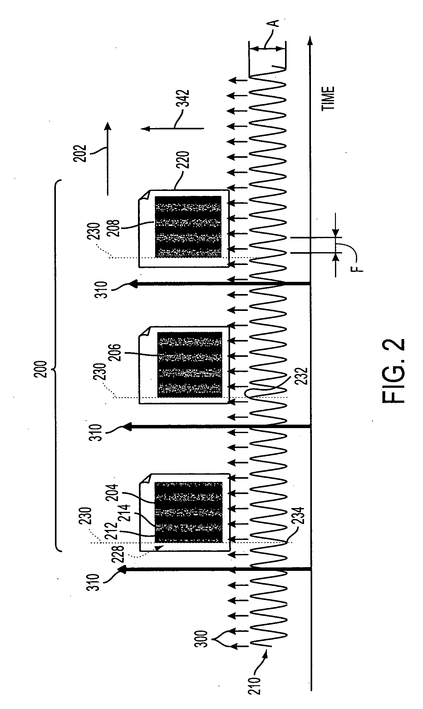
For example, the banding can occur due to a motion quality error due to runout of a roll, gear teeth meshing errors, ROS polygon once around errors, and the like.
However, the periodic bands are generally not synchronous with the image.
One approach to eliminate banding defects is to require the manufacture of parts / subsystems to meet tight tolerances which results in high costs.
However, the reference does not discuss measuring the image and using this information to improve or alleviate banding defect of the marking device.

Method used


Image

  • Systems and methods to measure banding print defects
  • Systems and methods to measure banding print defects
  • Systems and methods to measure banding print defects

Examples


Embodiment Construction

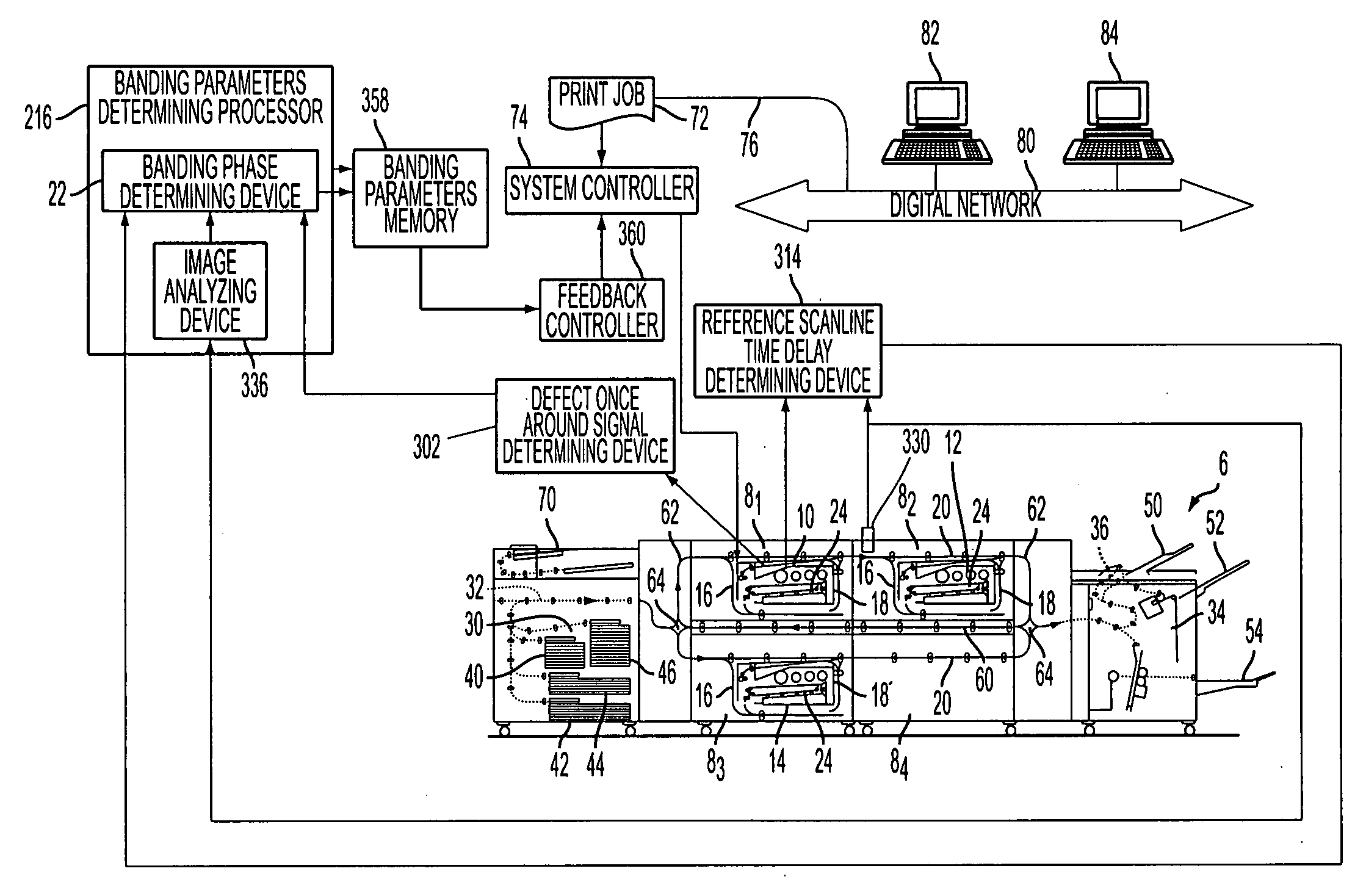
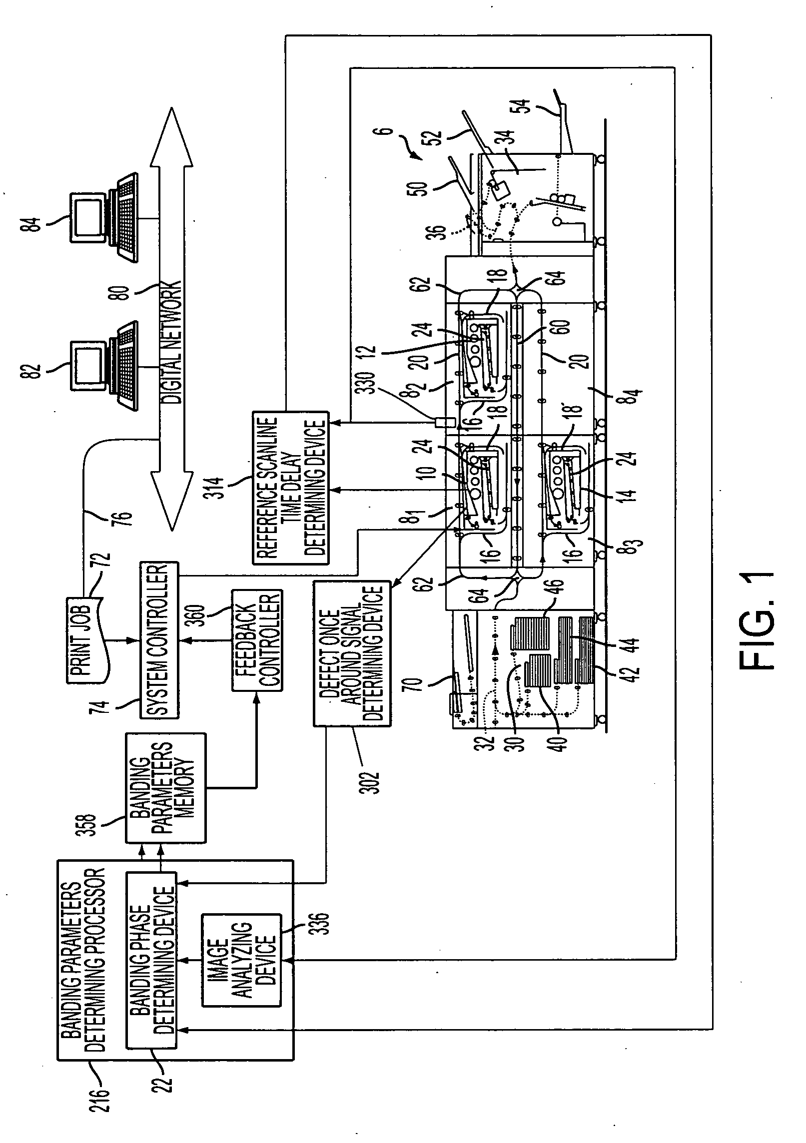
[0043] With reference to FIG. 1, an example printing or document processing system 6 includes first, second, . . . , nth marking engine processing units 81, 82, 83, . . . , 8n each including an associated first, second, . . . , nth marking or print engines or devices 10, 12, 14 and associated entry and exit inverter / bypasses 16, 18. In some embodiments, marking engines are removable. For example, in FIG. 1, an integrated marking engine and entry and exit inverter / bypasses of the processing unit 84 are shown as removed, leaving only a forward or upper paper path 20. In this manner, for example, the functional marking engine portion can be removed for repair, or can be replaced to effectuate an upgrade or modification of the printing system 6. While three marking engines 10, 12, 14 are illustrated (with the fourth marking engine being removed), the number of marking engines can be one, two, three, four, five, or more. Providing at least two marking engines typically provides enhanced ...


PUM


Abstract

A defect once around signal time period of a defect source inherent in a marking device is determined, the defect source having one or more banding frequencies. A reference scanline time delay, which is a time between a page sync signal and a writing of a reference scanline, is determined. A test target is written, sensed and analyzed. A reference scanline phase offset of each banding frequency relative to the reference scanline is determined. A banding phase of each banding frequency is determined based at least on the defect once around signal time period, reference scanline time delay and reference scanline phase offset.

Description

CROSS REFERENCE TO RELATED PATENTS AND APPLICATIONS [0001] The following patents / applications, the disclosures of each being totally incorporated herein by reference are mentioned: [0002] U.S. Pat. No. 6,973,286 (Attorney Docket A2423-US-NP), issued Dec. 6, 2005, entitled “HIGH RATE PRINT MERGING AND FINISHING SYSTEM FOR PARALLEL PRINTING,” by Barry P. Mandel, et al.; [0003] U.S. application Ser. No. 10 / 917,676 (Attorney Docket A3404-US-NP), filed Aug. 13, 2004, entitled “MULTIPLE OBJECT SOURCES CONTROLLED AND / OR SELECTED BASED ON A COMMON SENSOR,” by Robert M. Lofthus, et al.; [0004] U.S. Pat. No. 6,959,165 (Attorney Docket A2423-US-DIV), issued Oct. 25, 2005, entitled “HIGH RATE PRINT MERGING AND FINISHING SYSTEM FOR PARALLEL PRINTING,” by Barry P. Mandel, et al.; [0005] U.S. application Ser. No. 10 / 999,326 (Attorney Docket 20040314-US-NP), filed Nov. 30, 2004, entitled “SEMI-AUTOMATIC IMAGE QUALITY ADJUSTMENT FOR MULTIPLE MARKING ENGINE SYSTEMS,” by Robert E. Grace, et al.; [0006...

Claims


Application Information

Patent Timeline
Patent Type & Authority Applications(United States)
IPC IPC(8): H04N1/409
CPCG03G15/5062H04N1/6033H04N1/506G03G2215/00067
Inventor PAUL, PETER
Owner XEROX CORP
Why Eureka
Try Eureka