Uniderectional dc-dc converter

a dc-dc converter and unidirectional technology, applied in the direction of dc-dc conversion, power conversion systems, instruments, etc., can solve the problems of increasing the size and weight of the dc-dc converter, not being effective in increasing the capacity, and complicated dc-dc converters, etc., to reduce the size and weight of the converter, and reduce the capacitance

Inactive Publication Date: 2007-10-11
HITACHI LTD +1
View PDF9 Cites 34 Cited by
  • Summary
  • Abstract
  • Description
  • Claims
  • Application Information

AI Technical Summary

Benefits of technology

[0009]Another object of this invention is to provide a unidirectional DC-DC converter which uses an auxiliary inductor of a comparatively small capacitance and can reduce the size and weight of the converter.
[0018]Still another preferred embodiment of this invention can provide a unidirectional DC-DC converter which can have a very great capacitance without switching of supply current.

Problems solved by technology

This makes the DC-DC converter complicated and expensive.
This increases the size and weight of the DC-DC converter.
Further, since the main switching element is directly connected in series to the DC power supply, the power supply must perform switching and this is not effective in increasing the capacity.

Method used


Image

  • Uniderectional dc-dc converter
  • Uniderectional dc-dc converter
  • Uniderectional dc-dc converter

Examples


embodiment 1

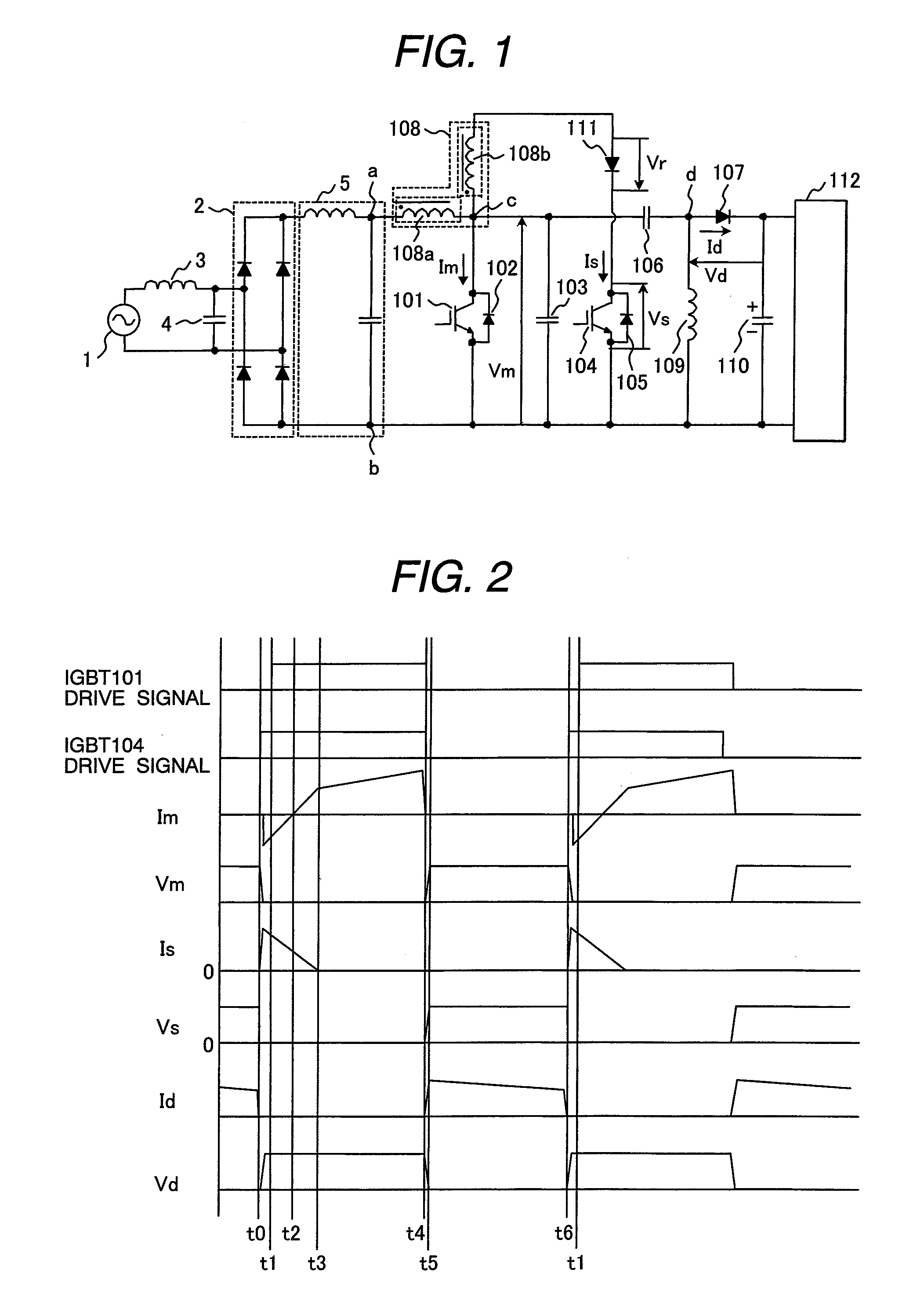
[0053]The first embodiment of this invention will be explained referring to FIG. 1 and FIG. 2.

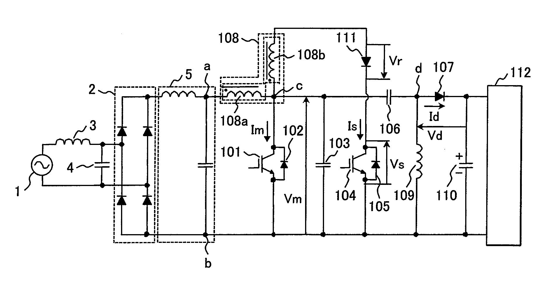
[0054]FIG. 1 shows the schematic diagram of the main circuit of the unidirectional DC-DC converter which is the first embodiment of this invention. This embodiment is a buck-boost type unidirectional DC-DC converter which enables both a step-up operation which outputs a voltage higher than an input voltage and a step-down operation which outputs a voltage lower than the input voltage.

[0055]The main circuit of FIG. 1 is equipped with commercial AC power supply 1, a filter circuit of inductor 3 and capacitor 4, rectification circuit 2, and high-frequency filter 5. AC voltage of commercial AC power supply 1 is filtered by a filter circuit made up of inductor 3 and capacitor 4, full-wave rectified by rectification circuit 2, and filtered into a smooth DC voltage by high-frequency filter 5 which is made up of an inductor and a capacitor.

[0056]A series circuit of main (first) inductor 108a and ma...

embodiment 2

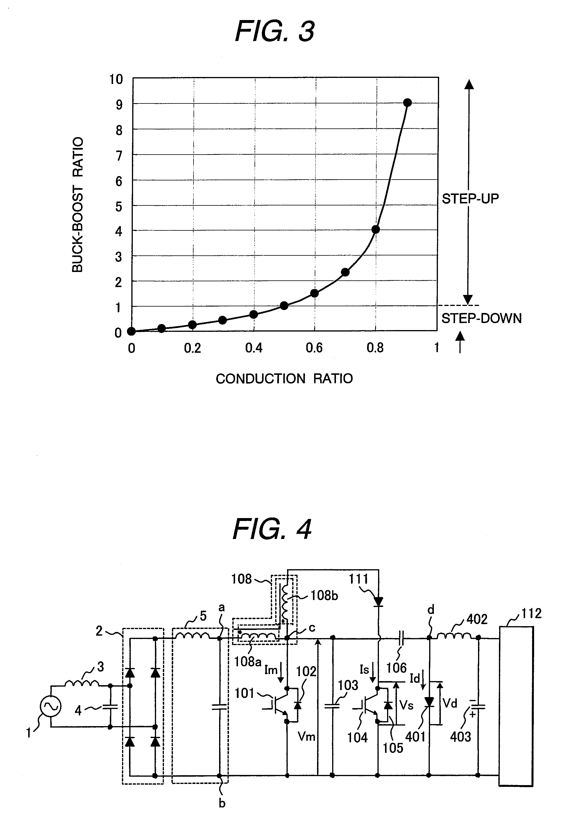
[0067]FIG. 4 shows the schematic diagram of the main circuit of the unidirectional DC-DC converter which is the second embodiment of this invention. This embodiment is also a buck-boost soft-switching type unidirectional DC-DC converter. Since elements of FIG. 4 are identical to those of FIG. 1, like elements are given like reference characters. The description of the elements is omitted if it is already given in Embodiment 1.

[0068]The second embodiment is the same as the first embodiment except for how to take out an output voltage from both ends “c” and “b” of main switching element IGBT101. The connection of diode 107 and third inductor 109 of FIG. 1 is reversed in the structure of FIG. 4. In other words, a series circuit of capacitor 106 and diode 401 is connected across main IGBT101 (between both ends “c” and “b”) and a series circuit of third inductor 402 and capacitor 110 is connected across this diode 401 (between both ends “d” and “b”). Both ends of this capacitor 110 are t...

embodiment 3

[0072]FIG. 5 shows the schematic diagram of the main circuit of the unidirectional DC-DC converter which is the third embodiment of this invention. This embodiment is also a buck-boost soft-switching type unidirectional DC-DC converter. Since elements of FIG. 5 are identical to those of FIG. 1 and FIG. 4, like elements are given like reference characters. The description of the elements is omitted if it is already given in the above embodiments.

[0073]In the main circuit of FIG. 5, a series circuit of main IGBT501 and main inductor 507a is connected across a DC power supply (between terminals of “a” and “b”). Diode 502 is back-to-back connected to main IGBT501 and snubber capacitor 503 is connected in parallel to main IGBT501. A series circuit of capacitor 106 and diode 508 is connected across main inductor 507a (between ends “e” and “b”). A series circuit of third inductor 509 and capacitor 110 is connected across this diode 508 (between ends “d” and “b”). Both ends of this capacito...


PUM


Abstract

A unidirectional DC-DC converter which has a simple control circuit without using multiple insulated power supplies, uses an auxiliary inductor of a comparatively small capacitance, reduces the size and weight of the converter, and has a very great capacitance without switching of supply current.A unidirectional DC-DC converter equipped with main IGBT101 which supplies and shuts off current for first inductor 108a and diode 107 which discharges energy from main inductor 108a to an output, wherein the DC-DC converter is further equipped with auxiliary IGBT104 which applies current to back-to-back-connected diode 102 by using energy stored in auxiliary inductor 108b which is magnetically coupled with main inductor 108a. This applies current to the back-to-back-connected diode in a short period including a time period in which the first switching element is turned on and accomplishes ZVZCS.

Description

CLAIM OF PRIORITY[0001]The present application claims priority from Japanese application serial No. 2006-105256, filed on Apr. 6, 2006, the content of which is hereby incorporated by reference into this application.FIELD OF THE INVENTION[0002]This invention relates to a unidirectional DC-DC converter which converts a supplied voltage into the other voltage.BACKGROUND OF THE INVENTION[0003]A unidirectional DC-DC converter which converts a supplied voltage into a desired voltage can increase the conversion efficiency by reducing switching losses by soft switching technology. Simultaneously, it is possible to downsize inductors, capacitors, and other passive elements by increasing driving frequencies of switching elements.[0004]Japanese Patent Laid-open No. 2005-318766 (Patent Document 1) discloses a unidirectional DC-DC converter which can perform soft switching. In the main circuit of the DC-DC converter, main switching element is directly connected to a DC power supply. An inductor ...

Claims


Application Information

Patent Timeline
Patent Type & Authority Applications(United States)
IPC IPC(8): H02M3/335
CPCH02M3/158
Inventor URUNO, JUNPEISHOJI, HIROYUKIKANOUDA, AKIHIKOKAMINAGA, YASUO
Owner HITACHI LTD
Why Eureka
Try Eureka