
Image Processing Device

Active Publication Date: 2007-10-11
PANASONIC SEMICON SOLUTIONS CO LTD
View PDF18 Cites 24 Cited by
  • Summary
  • Abstract
  • Description
  • Claims
  • Application Information

AI Technical Summary

Benefits of technology

[0007] According to the present invention, the gray image and the distance image of the object can be obtained from the electrical output corresponding to the intensity of the light received by the light receiving element at a time. In addition, since each of the gray values of the gray image and a corresponding distance value of the distance image are obtained from the same pixel, no treatment of associating each of positions in the gray image with the corresponding distance value is needed. Consequently, it is possible to obtain a greater amount of the spatial information by using both of the gray image and the distance image without performing such a complex associating treatment. Furthermore, as compared with the case of combining a conventional image pickup device for generating only the gray image with a conventional distance measuring device for extracting the distance information, there are another advantages of downsizing the device as a whole, and achieving a cost reduction.
[0014] As another preferred embodiment of the present invention, the image processing device further comprises an object extractor configured to extract the object having a predetermined shape from the gray image generated by the image generator, and the measuring-point determining unit determines a plurality of measuring points on the object extracted by the object extractor, and the distance calculator calculates the actual distance between two of the determined measuring points. In this case, since it is not needed to allow the user to designate the measuring points, the actual size of the predetermined portion of the object can be automatically calculated. In addition, it is possible to reduce variations in measurement results of the actual size, as compared with the case that the measuring points are designated every time by the user.

Problems solved by technology

For example, since a light is scanned in a target space in the apparatus using the triangular surveying method, a relatively large time lag between the generation of the gray image and the generation of the distance information occurs, so that the associating treatment therebetween becomes complex.
In addition, when using both of the device for generating the gray image such as a TV camera with a CCD image sensor and the device for detecting the distance information such as the position sensitive detector, an increase in size and cost of the whole apparatus also becomes a problem.

Method used


Image

  • Image Processing Device
  • Image Processing Device
  • Image Processing Device

Examples


first embodiment

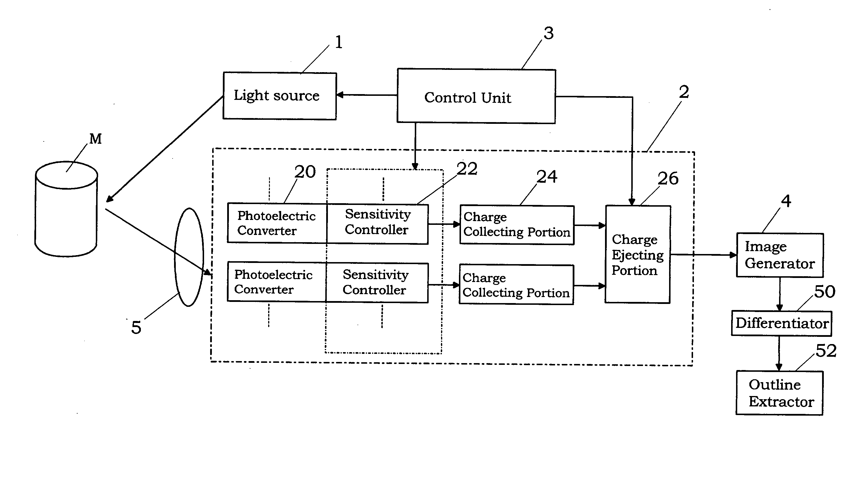
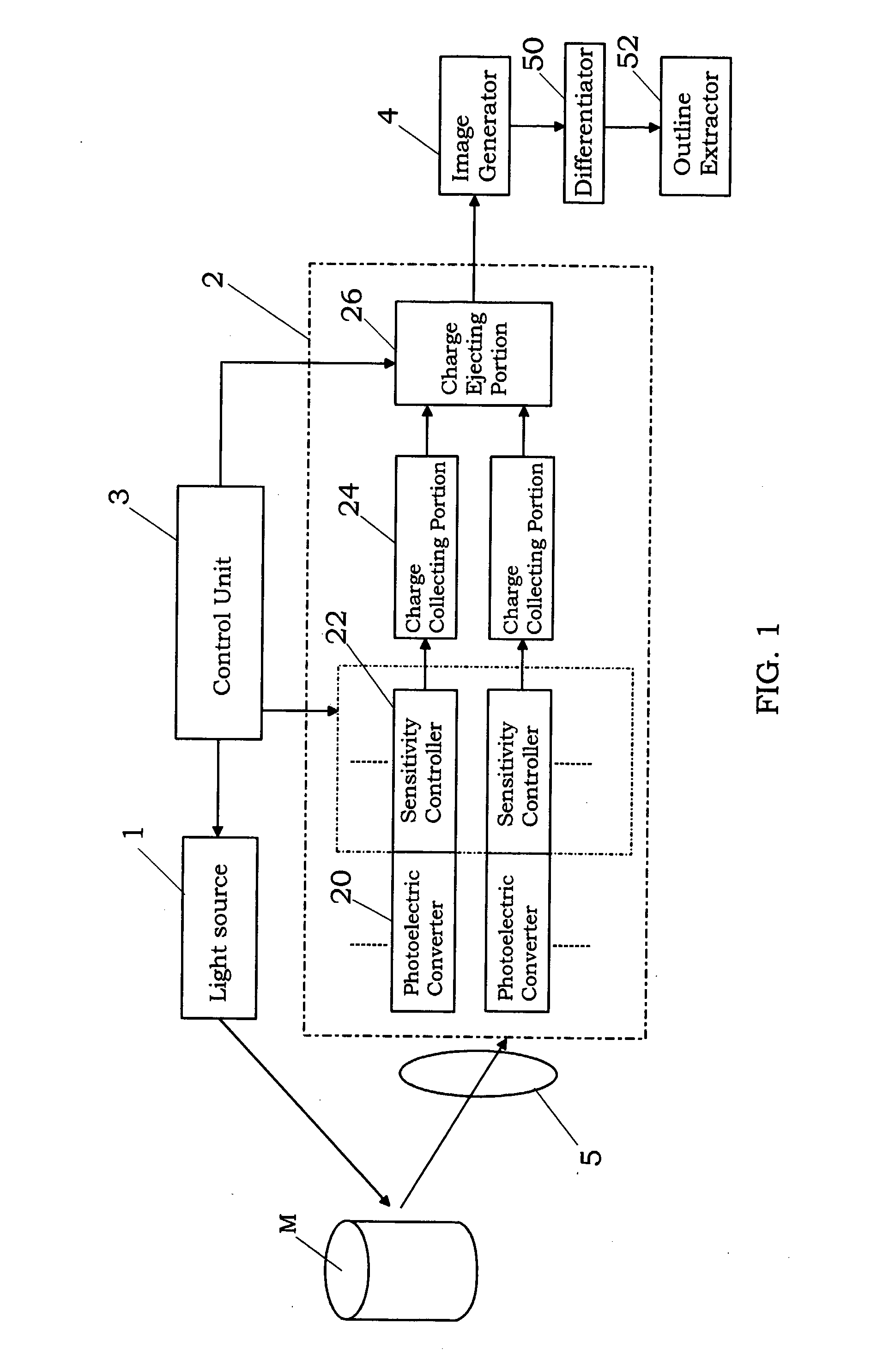
[0034] As shown in FIG. 1, an image processing device of the present embodiment comprises a light source 1 for irradiating a light into a target space, light receiving element 2 for receiving the light reflected from an object M such human in the target space, control unit 3 for the light receiving element, image generator 4 for generating a distance image and a gray image from an output of the light receiving element 2, differentiator 50 for generating a distance differential image from the distance image and a gray differential image from the gray image, and an outline extractor 52 for extracting an outline of the object M by use of the distance differential image and the gray differential image.

[0035] The present invention is based on the premise that a distance between the light source 1 and the object M is determined from a time of flight, which is defined a time period elapsed between the irradiation of the light from the light source and the reception of the light reflected ...

second embodiment

[0069] An image processing device of the second embodiment is substantially the same as the device of the first embodiment except that an object detector 54 is provided in place of the outline extractor 52, as shown in FIG. 9. Therefore, the same components as the components of FIG. 1 are indicated by the same numerals, and duplicate explanations are omitted.

[0070] The object detector 54 detects the object M according to the following method with use of an output of the differentiator 50, i.e., a gray differential image. The image generator 4 generates the gray image in a time-series manner. Therefore, a plurality of gray images are obtained at different times. The object detector 54 generates a difference image between a pair of gray differential images, which are generated from two of the gray images, and then extracts a region where each of pixel values is not smaller than a threshold value in the difference image. The thus extracted region corresponds to a region of the object ...

third embodiment

[0081] An image processing device of the third embodiment is substantially the same as the device of the first embodiment except for the following components. Therefore, the same components as the components shown in FIG. 1 are indicated by the same numerals, and duplicate explanations are omitted.

[0082] The image processing device of this embodiment is characterized by comprising an actual-size calculator 62 for determining an actual size of a desired portion of the object by use of the distance image and the gray image generated by the image generator 4, shape estimating unit 64 for estimating a shape of the object M, and a volume estimating unit 66 for estimating a volume of the object.

[0083] As shown in FIG. 11, the distance image generated by the image generator 4 is sent to a measuring point determining unit 60. In the measuring-point determining unit 60, a plurality of measuring points are designated in the gray image. The measuring points can be designated in the gray imag...


PUM


Abstract

An image processing device for generating both of a distance image and a gray image from an electrical output of a light receiving element on the precondition that a light intensity-modulated at a modulation frequency is irradiated into a target space. This device has an image generator for generating the distance image having pixel values, each of which provides a distance value between an object in the target space and the device, in accordance with a phase difference between the irradiated light and the received light, and the gray image having pixel values, each of which provides a gray value of the object, in accordance with an intensity of the received light. By use of an output of the image generator, an outline of the object can be extracted.

Description

TECHNICAL FIELD [0001] The present invention relates to an image processing device for extracting spatial information form a target space, into which an intensity-modulated light is irradiated. BACKGROUND ART [0002] In the past, various types of spatial information detecting devices for measuring distance information of an object or extracting an outline of the object from an output of image pickup means have been proposed. For example, Japanese Patent Publication Laid-open No. 11-284997 discloses a technique of extracting the outline of the object from a gray image generated by use of an image sensor. In addition, Japanese Patent Publication Laid-open No. 64-10108 discloses a technique of determining a distance with the object by irradiating a spot-like or linear light pattern to an object, receiving a light reflected from the object by a position sensitive detector (PSD), and converting an output of the position sensitive detector into the distance in accordance with a triangular ...

Claims


Application Information

Patent Timeline
IPC IPC(8): G01S17/36
CPCG01S17/36G01S17/89G01S17/88
Inventor HAGIO, KENICHIIKARI, MOTOOTAKADA, YUJIHASHIMOTO, YUSUKETSUNESADA, FUMI
Owner PANASONIC SEMICON SOLUTIONS CO LTD
Learn More