Sacrificial inner shroud liners for gas turbine engines

a technology for gas turbine engines and inner shrouds, which is applied in the direction of machines/engines, liquid fuel engines, forging/pressing/hammering apparatus, etc., can solve the problems of extreme vibrations due to normal use at operating speeds, components that may experience wear in the engine, and the operating environment of a turbofan engine and its various components is extremely harsh, so as to reduce weight

Active Publication Date: 2007-10-11
RAYTHEON TECH CORP
View PDF3 Cites 11 Cited by
  • Summary
  • Abstract
  • Description
  • Claims
  • Application Information

AI Technical Summary

Benefits of technology

[0008] It is an object of the present invention...

Problems solved by technology

The operating environment for a turbofan engine and its various component is extremely harsh.
The vibrations due to normal use at operating speeds are extreme.
One of the many components that may experience wear in the engine due to vibrations and high temperature are the variable vanes' inner trunnions.
During wear, the carb...

Method used


Image

  • Sacrificial inner shroud liners for gas turbine engines
  • Sacrificial inner shroud liners for gas turbine engines
  • Sacrificial inner shroud liners for gas turbine engines

Examples


Embodiment Construction

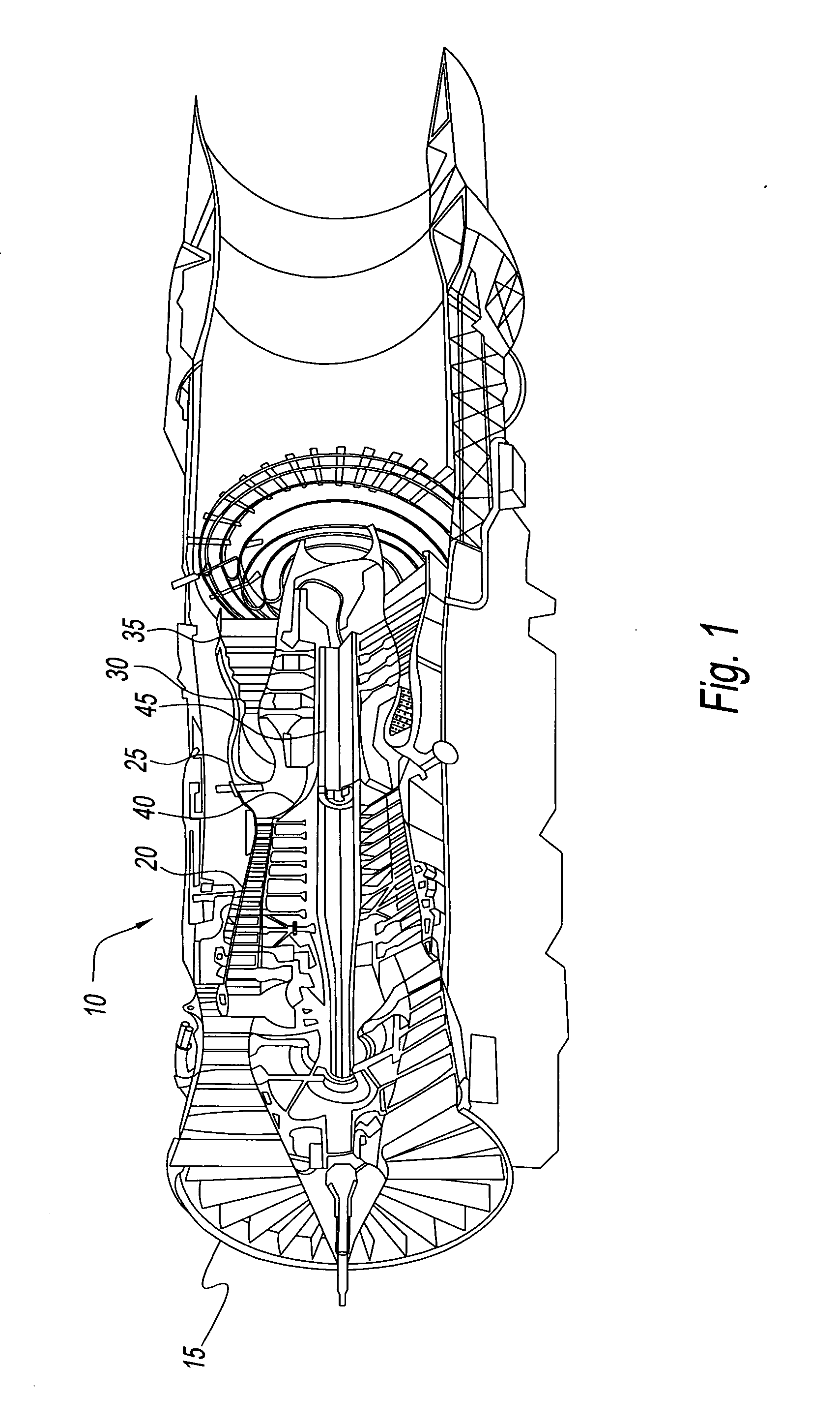
[0027] Referring to the drawings, and in particular to FIG. 1. An axial flow gas turbine engine 10 used for powering an aircraft in flight or powering an electrical generator, is shown. Engine 10 typically includes, in serial flow communication, a fan module 15, a high pressure compressor 20, a combustor 25, a high pressure turbine 30, and a low pressure turbine 35. Combustor 25 generates combustion gases that are channeled in succession to high pressure turbine 30 where they are expanded to drive the high pressure turbine 30, and then to the low pressure turbine 35 where they are further expanded to drive the low pressure turbine 35. High pressure turbine 30 is drivingly connected to the high pressure compressor 20 via a first rotor shaft 40, and low pressure turbine 35 is drivingly connected to the fan module 15 via a second rotor shaft 45.

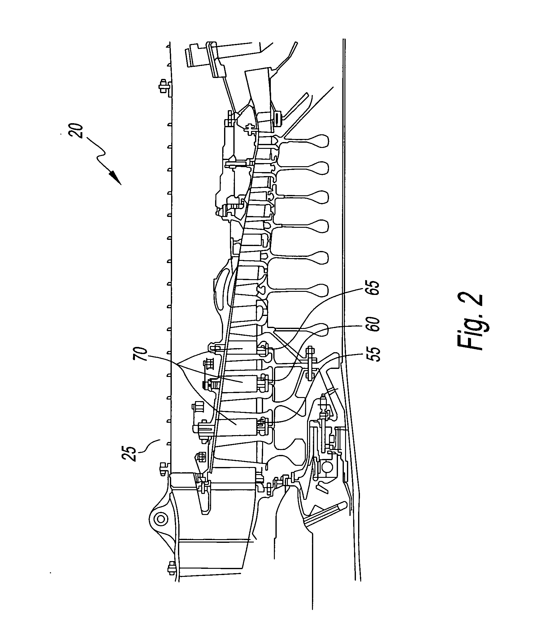
[0028] Referring to FIGS. 2 and 3, high pressure compressor 20 typically includes a series of variable 55, 60 and 65 and fixed stator vane sta...


PUM

PropertyMeasurementUnit
Diameteraaaaaaaaaa

Abstract

A split shroud system for a gas turbine engine having a pair of annular-shaped shrouds that each have an inner pocket; to form a pair of inner pockets. Each of the pair of pockets having liner parts that form a circle. Liner parts of one of the pair of pockets facing liner parts of the other of the pair of pockets to form liner part pairs. One of each of said of pair of liner parts has a mutual abutting surface that forms a plurality of slots for accepting a plurality of vane inner trunnions.

Description

STATEMENT REGARDING FEDERALLY SPONSORED RESEARCH OR DEVELOPMENT [0001] This invention was made with Government support under F33615-99-D-2051-0010 awarded by the United States Air Force. The Government has certain rights in this invention.BACKGROUND OF THE INVENTION [0002] 1. Field of the Invention [0003] The present invention relates to a shroud for a gas turbine engine. More particularly, the present invention relates to an inner liner for a shroud for a gas turbine engine. Still more particularly, the present invention relates to an inner graphitic carbon liner that is received in a shroud of a gas turbine engine to reduce the overall engine weight and cost and vane trunnion wear. [0004] 2. Description of Prior Art [0005] The operating environment for a turbofan engine and its various component is extremely harsh. The vibrations due to normal use at operating speeds are extreme. The operating temperature of some of the components are also extremely high. One of the many component...

Claims


Application Information

Patent Timeline
IPC IPC(8): F01D9/00
CPCF01D17/162F04D29/563Y10T29/49323F05D2300/509F05D2300/224Y02T50/671Y02T50/60F01D11/22F01D11/08F02C7/28
Inventor LYTLE, WILLIAM C.
Owner RAYTHEON TECH CORP
Why Eureka
Try Eureka