Chest expander

a chest expander and expander technology, applied in the field of chest expanders, can solve the problems of users' major complaints about the durability and lifespan of the chest expander, and achieve the effect of simple structur

Inactive Publication Date: 2007-10-11
AN TAE JIN
View PDF98 Cites 22 Cited by
  • Summary
  • Abstract
  • Description
  • Claims
  • Application Information

AI Technical Summary

Benefits of technology

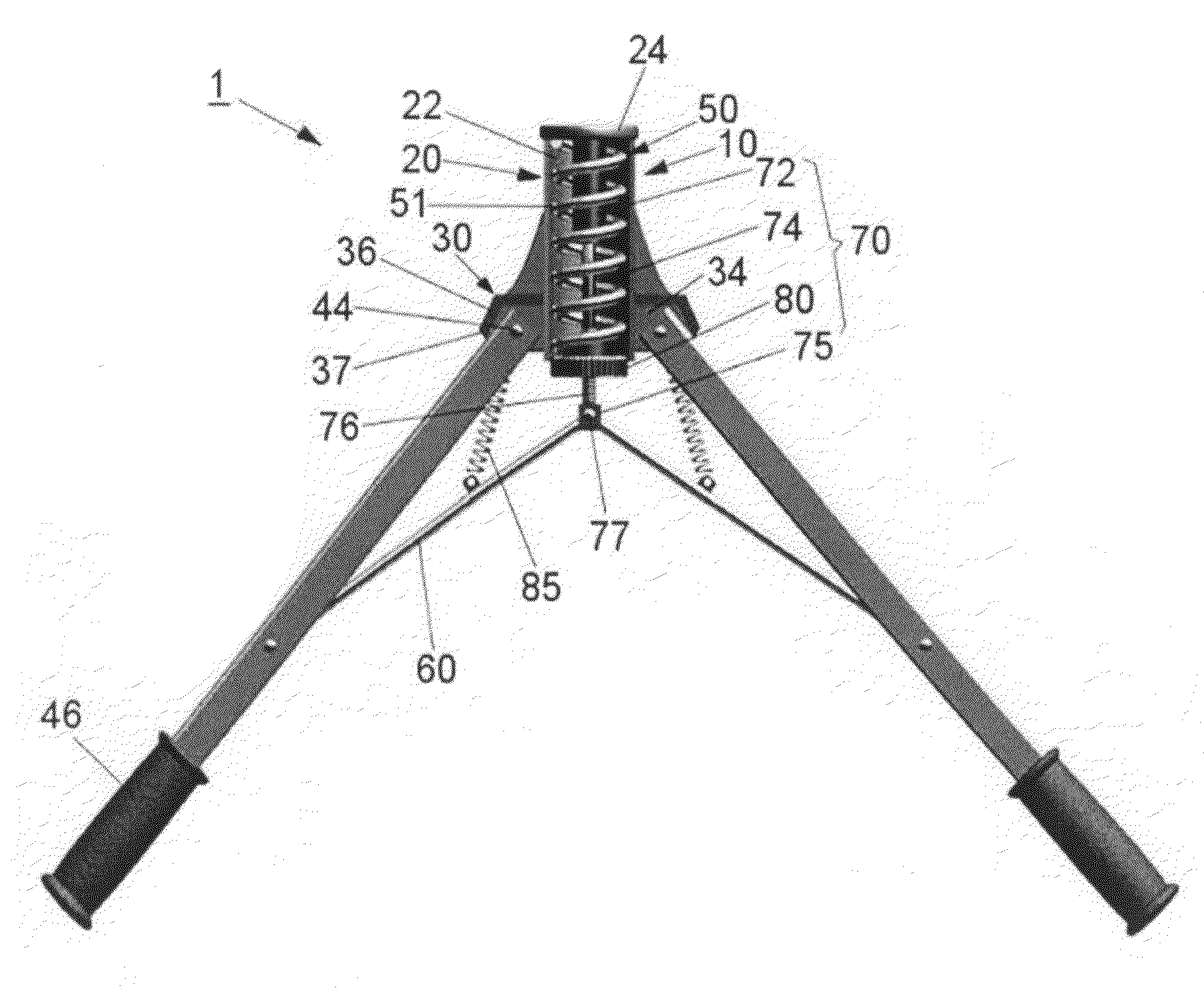
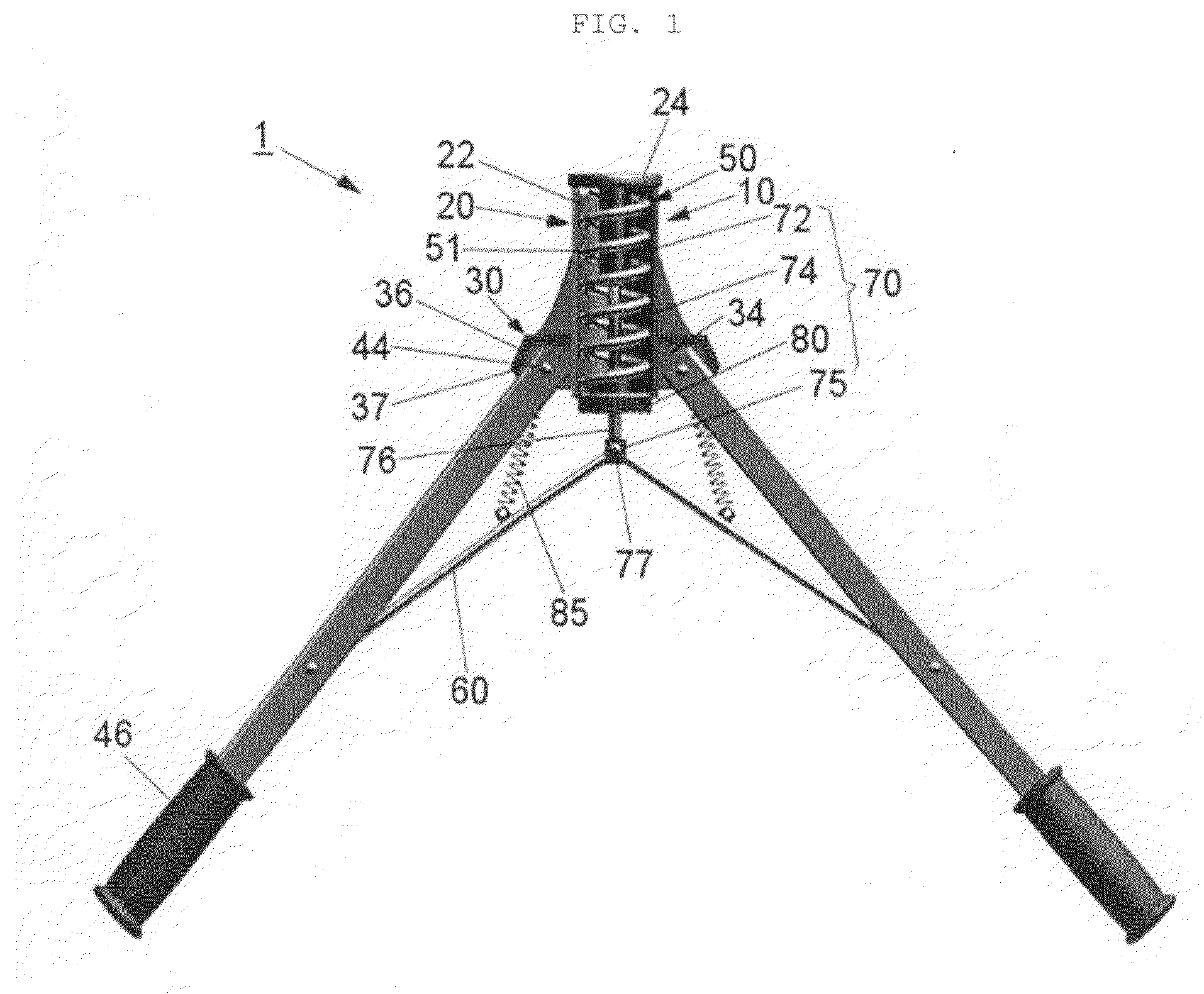
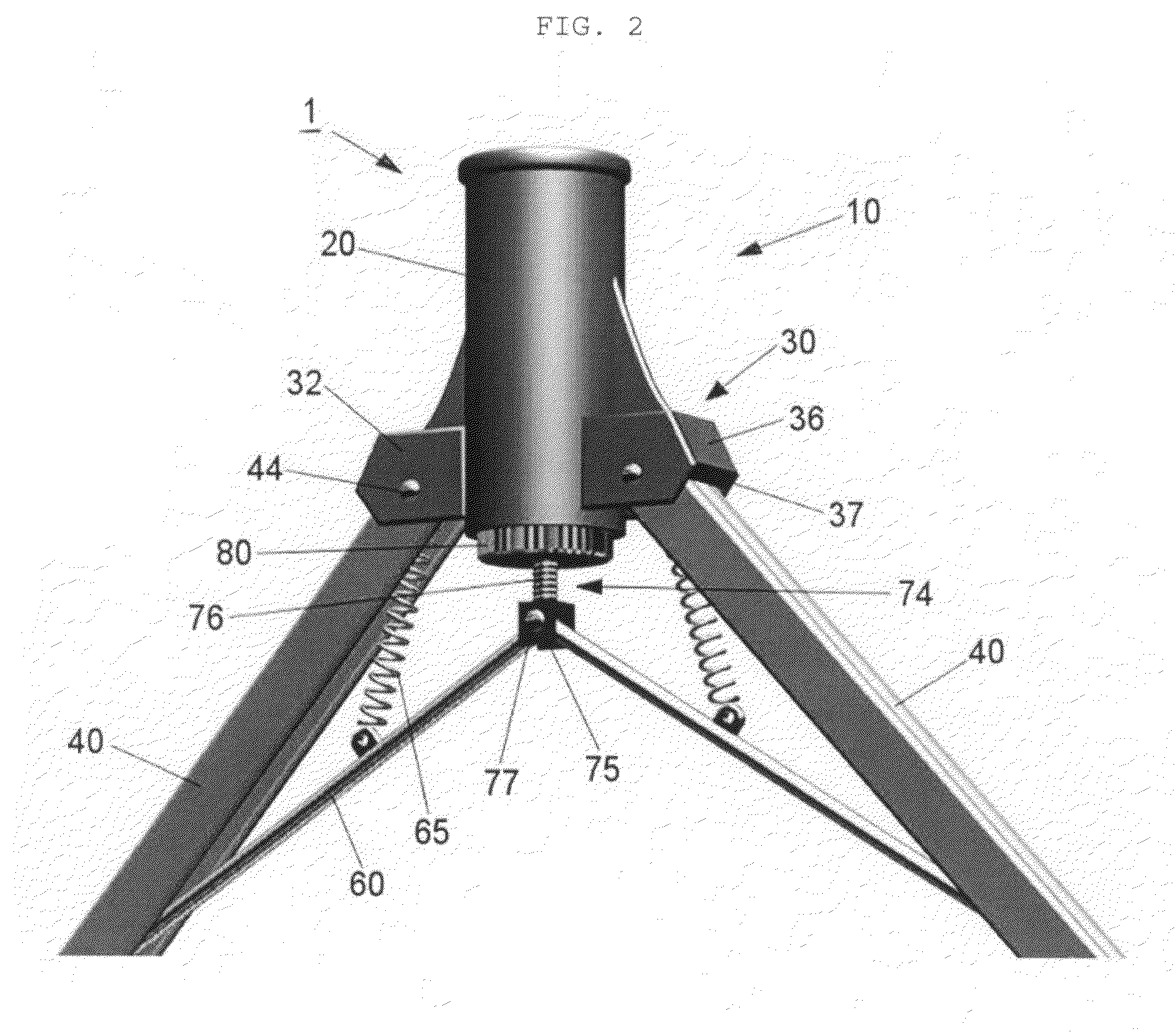
[0008]The present invention provides a chest expander capable of compressing a spring installed at a head using powers added by a pair of arms to uniformly distribute a resilient force to the pair of arms using a simple structure.

Problems solved by technology

As a result, a reduction in durability and lifespan of the chest expander may be a major complaint of users.

Method used


Image

  • Chest expander
  • Chest expander
  • Chest expander

Examples


first embodiment

[0048]Upper parts 142 of the arms 140 are pivotally connected to the arm connection parts 130 disposed at both sides of the head 110 by hinge pins 144, respectively. The arms 140 include grip parts formed at their lower ends, similar to the first embodiment shown in FIGS. 1 and 2.

[0049]The spring installation part 120 of the head 110 is formed of a hollow cylindrical part 122 having a lower open end and vertically extending therefrom to accommodate a gas spring 151 as a spring member 150. In accordance with the second exemplary embodiment of the present invention, the spring member 150 is formed of a compression gas spring 151. The gas spring 151 includes a rod part 152, and a cylinder part 153. The rod part 152 is connected to a piston (not shown) disposed in the cylinder part 153 to extend to the exterior of the cylinder part 152. Therefore, the gas spring 151 provides a resilient force to push the rod part 152 downward corresponding to a compression distance in which the rod part...

fourth embodiment

[0064]Referring again to FIGS. 10 to 12 showing the fourth embodiment, a spring operation part for receiving movement of the arms 240 and compressing the coil spring 251 includes a connection rod having a head part 281 and a link connection part disposed under the head part, may include a pressing piece 271.

[0065]The compression spring 250 is installed in the hollow cylindrical part 222 constituting the spring installation part 220. In the fourth embodiment, the compression spring 250 includes a plurality of coil springs 251.

[0066]Upper ends of the plurality of coil springs 251 are supported by the pressing piece 271. As the pressing piece 271 moves upward and downward in a longitudinal direction of the hollow cylindrical part 222, the coil springs 251 are compressed or recovered.

[0067]The head part 281 is supported by an upper surface of the pressing piece 271 to receive a force pulled by the connection rod connected to the head part 281, thereby lowering the pressing piece 271.

[00...


PUM


Abstract

Provided is a chest expander including: a head having a spring installation part at which a spring is installed and arm connection parts installed at both sides of the spring installation part; a pair of arms pivotally coupled with the arm connection parts of the head at their upper ends; a spring member vertically installed at the spring installation part of the head, and converting movement of the pair of arms approached toward each other into a resilient force generated by compressing or extending the spring to vertically transmit the resilient force to the arms; a pair of links having first ends connected to each arm and second ends extending between the arms; and a spring operation part having a link connection part connected to the second ends of the links and compressing or extending the spring member using power added and transmitted to the link connection part through the links by the movement of the arms.

Description

BACKGROUND OF THE INVENTION[0001]1. Field of the Invention[0002]The present invention relates to a chest expander.[0003]2. Description of the Related Art[0004]A chest expander is one of sporting goods used for exercising arms and shoulders. The chest expander is operated by gripping both grip parts formed at lower ends of a pair of arms of the chest expander, using both hands of a user. The user pushes the both arms to approach the arms toward each other, and releases the both arms to space them apart from each other, thereby exercising his / her arms, chest and shoulders. The user can repeat the above movement to increase his / her arm and shoulder muscle power.[0005]A conventional chest expander uses a tension coil spring to use the muscle power when the user pushes the both arms to approach them together. That is, when the arms come toward each other, the coil spring is extended to apply a power in an opposite direction of the movement of the user, thereby exercising his / her muscle p...

Claims


Application Information

Patent Timeline
Patent Type & Authority Applications(United States)
IPC IPC(8): A63B21/02
CPCA63B21/0004A63B21/0087A63B23/12A63B21/05A63B21/1492A63B21/023A63B21/4047A63B23/03533A63B21/4035A63B21/055A63B21/02
Inventor JIN, AN TAE
Owner AN TAE JIN
Why Eureka
Try Eureka