
System and method for ultrasonic detection and imaging

a technology of ultrasonic detection and imaging, applied in the field of data processing systems and methods, can solve the problems of high-speed sampling rate, known systems and methods utilizing such detectors, and possible causes of ultrasonic energy, and achieve the effect of facilitating a thorough and repeatable tes

Inactive Publication Date: 2007-10-11
CATERPILLAR INC
View PDF13 Cites 9 Cited by
  • Summary
  • Abstract
  • Description
  • Claims
  • Application Information

AI Technical Summary

Benefits of technology

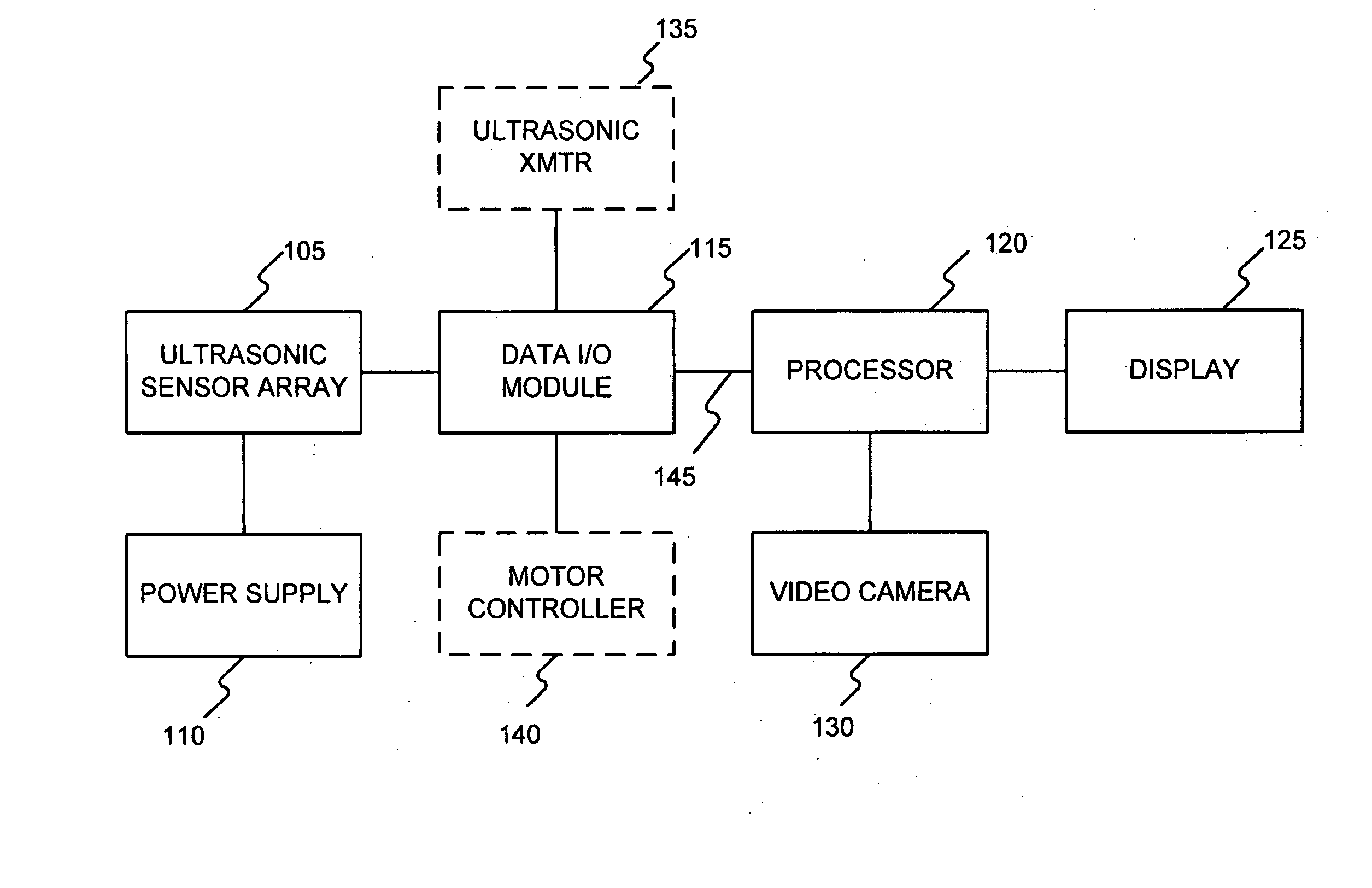
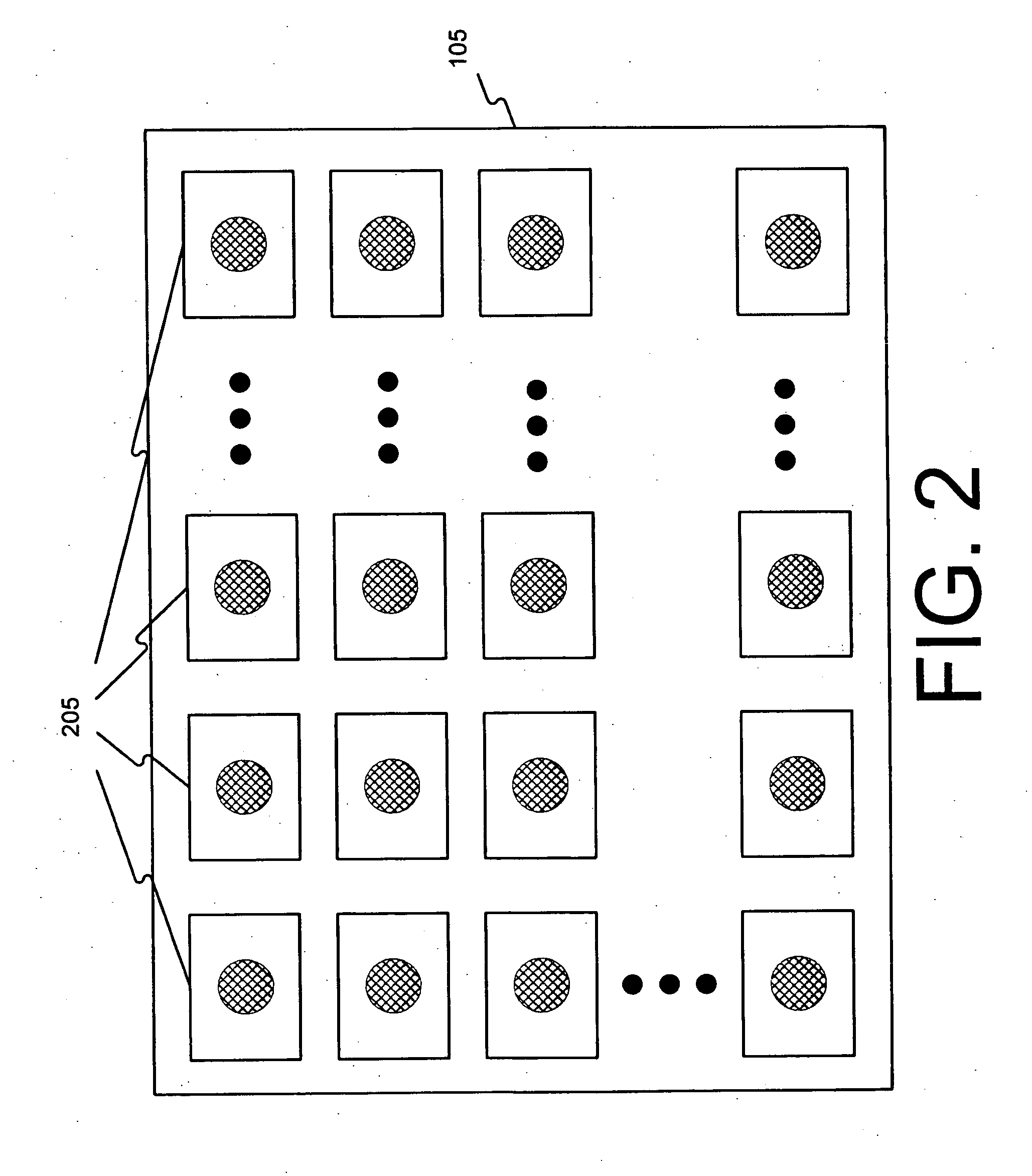
The invention is a system and method for detecting ultrasonic energy using an array of ultrasonic sensors. The sensors collect data on the ultrasonic energy, which is then processed by RMS-to-DC conversion. This approach eliminates the need for high-speed analog-to-digital conversion. The system can also output a contour map based on the detected ultrasonic energy and blend it with a visible image, making the display more intuitive and useful to an operator. The system can also reposition the ultrasonic sensors to facilitate a thorough and repeatable test. Overall, the invention provides a more efficient and effective way to detect and measure ultrasonic energy.

Problems solved by technology

Alternatively, ultrasonic energy may be caused by a mechanical vibration, such as that caused by an excessively-worn bearing or by missing teeth on a gear drive assembly.
Known systems and methods utilizing such detectors have many disadvantages, however.
For instance, because of the signal frequencies involved, known systems may utilize very high-speed sampling rates that increase the expense of data acquisition hardware.
Furthermore, known detection systems do not provide user-friendly outputs.
For example, such systems may not support imaging at all.
And known systems that do provide imaging of the ultrasonic energy may not sufficiently relate the detected source of ultrasonic energy to the surrounding environment in a way that allows for a targeted response to the detection event.
Moreover, known detection systems and methods may be limited to a narrow Field-Of-View (FOV) without a structured way to fully screen a Unit Under Test (UUT) that occupies an area that is many times the size of the detector's FOV.

Method used


Image

  • System and method for ultrasonic detection and imaging
  • System and method for ultrasonic detection and imaging
  • System and method for ultrasonic detection and imaging

Examples


first embodiment

[0061]FIG. 8A is an illustration of a test environment, according to the invention. As shown therein, a hollow cubic cover 810 having one open end may be raised or lowered in a vertical direction 815 over a UUT 705 to enclose the UUT 705 during test. One or more ultrasonic sensor arrays 105 may be attached to one or more interior surfaces of the cubic cover 810. Accordingly, the UUT 705 can be inspected from one or more perspectives during a test procedure. Moreover, a benefit of the cubic cover 810 is that it shields background noise, thereby improving signal-to-noise ratio (SNR) at the one or more ultrasonic sensor arrays 105.

second embodiment

[0062]FIG. 8B is an illustration of a test environment, according to the invention. As shown therein, a hemispherical cover 820 may be positioned over the UUT 705 along a vertical axis 815. An inner surface of the hemispherical cover 820 may include one or more ultrasonic sensor arrays 105. Like cubic cover 810, the hemispherical cover 820 shields the UUT 705 from background noise during test, thereby improving signal-to-noise ratio (SNR) at the one or more ultrasonic sensor arrays 105.

[0063] As described above with reference to FIGS. 8A and 8B, a test environment may utilize more than one ultrasonic sensor array 105. Systems utilizing multiple sensor arrays 105 may be configured to switch between one or more of the multiple sensor arrays 105 during test. Moreover, where multiple sensor arrays 105 are implemented, one or more of the sensor arrays 105 could be sensitive to energy outside of the ultrasonic frequency range.

[0064] In embodiments of the invention, it may be advantageous...

third embodiment

[0065]FIG. 9A is an illustration of a test environment, according to the invention. As illustrated therein, a UUT 705 may be rotated about a vertical axis 910 using a carousel 905. Carousel 905 may be driven by a stepper motor (not shown), which may be controlled by motor controller 140. The benefit of such repositioning is that different views of the UUT 705 may be presented to the fixed sensor array 705. Moreover, such changing views are under precise and repeatable control.


PUM


Abstract

Systems and Methods are disclosed for the detection and imaging of ultrasonic energy. Embodiments of the invention utilize an array of ultrasonic sensors where data from each of the sensors are processed by RMS-to-DC conversion. In addition, embodiments of the invention output a contour map based on detected ultrasonic energy and blend at least one feature of the contour map with a feature of a visible image so that a blended image can be displayed to an operator. Furthermore, embodiments of the invention provide a system and method for repositioning an array of ultrasonic sensors with respect to target area or Unit Under Test (UUT) to facilitate a thorough and repeatable test.

Description

TECHNICAL FIELD [0001] This disclosure relates generally to data processing systems and methods, and more particularly, but without limitation, to systems and methods related to detection, imaging, and / or other processing associated with ultrasonic energy. BACKGROUND [0002] A practical application for the detection and imaging of ultrasonic energy is to locate, by inference, ultrasonic energy sources. Such sources may be, for instance, a gas or fluid escaping from a pressurized container (in other words, a leak). Alternatively, ultrasonic energy may be caused by a mechanical vibration, such as that caused by an excessively-worn bearing or by missing teeth on a gear drive assembly. [0003] Piezoelectric and other detectors are known for detecting ultrasonic energy emissions. Known systems and methods utilizing such detectors have many disadvantages, however. For instance, because of the signal frequencies involved, known systems may utilize very high-speed sampling rates that increase...

Claims


Application Information

Patent Timeline
Patent Type & Authority Applications(United States)
IPC IPC(8): A61B8/00
CPCG03B29/00G01M3/24
Inventor CLARKE, BURTON ROLANDALLGAIER, RYAN PAUL
Owner CATERPILLAR INC
Learn More