
Systems and methods for loading a prosthesis onto a minimally invasive delivery system

Inactive Publication Date: 2007-10-11
BAE SYST INFORMATION & ELECTRONICS SYST INTERGRATION INC +1
View PDF104 Cites 338 Cited by
  • Summary
  • Abstract
  • Description
  • Claims
  • Application Information

AI Technical Summary

Benefits of technology

[0008] The present invention relates generally to the loading of a transluminally implantable prosthetic valve onto a delivery catheter, or other delivery system, for a minimally invasive implantation of the prosthesis into the vasculature at a location remote from the implantation site. Preferred embodiments of the present invention preferably are used with a self-expanding prosthesis, but may also be useful in connection with balloon-expandable or other mechanically-expanded prostheses. Desirably, preferred embodiments of the present invention permit the reduction of an external dimension of a compressible valve prosthesis without damaging the valve. Preferably, the system and method properly orient the valve relative to the frame of the prosthesis prior to or during reduction of the external dimension.

Problems solved by technology

This procedure has the disadvantage of requiring prolonged patient hospitalization, as well as extensive and often painful recovery.
It also presents advanced complexities and significant costs.
While it is known to load an expandable stent onto a delivery catheter and deliver the stent using the delivery catheter, such systems are not readily adaptable for use with prosthetic valve assemblies.
For example, present systems for loading expandable stents onto a delivery catheter are prone to damaging the valve portion of the prosthetic valve assembly when used in connection with a prosthetic valve assembly.

Method used


Image

  • Systems and methods for loading a prosthesis onto a minimally invasive delivery system
  • Systems and methods for loading a prosthesis onto a minimally invasive delivery system
  • Systems and methods for loading a prosthesis onto a minimally invasive delivery system

Examples


Embodiment Construction

[0041] Although there has been considerable development and refinement of vascular stent concepts in relationship to the coronary vasculature for the treatment of myocardial infarction and angina, these concepts do not necessarily translate to prosthetic structures involving larger sections of vasculature, and more specifically, implants incorporating prosthetic valves for minimally invasive delivery from peripheral access sites of the body. For example, although a small delivery profile, or small cross-sectional configuration, is desirable for both coronary stents and prosthesis valves, the expanded size and the implantation location of prosthesis valves may introduce difficulties into the loading of a prosthesis onto a catheter or other minimally invasive delivery system.

[0042] In particular, a valve prosthesis typically requires significant reduction of the expanded external dimension in order to be loaded onto a delivery device, such as a catheter. In contrast, a typical corona...


PUM


Abstract

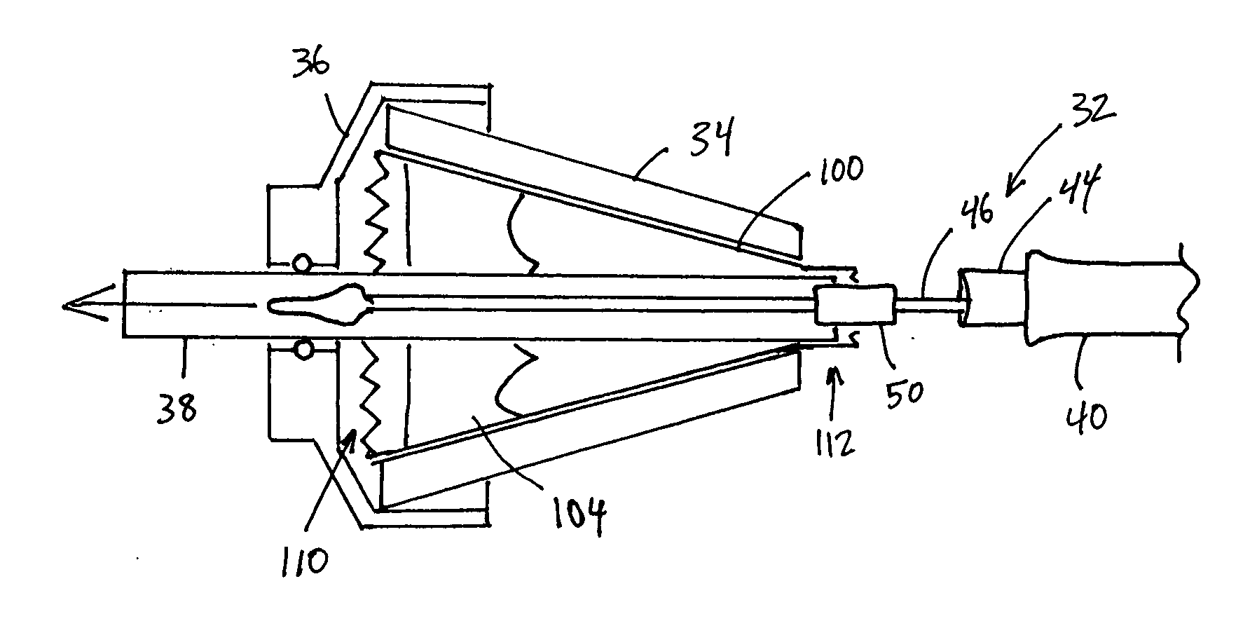
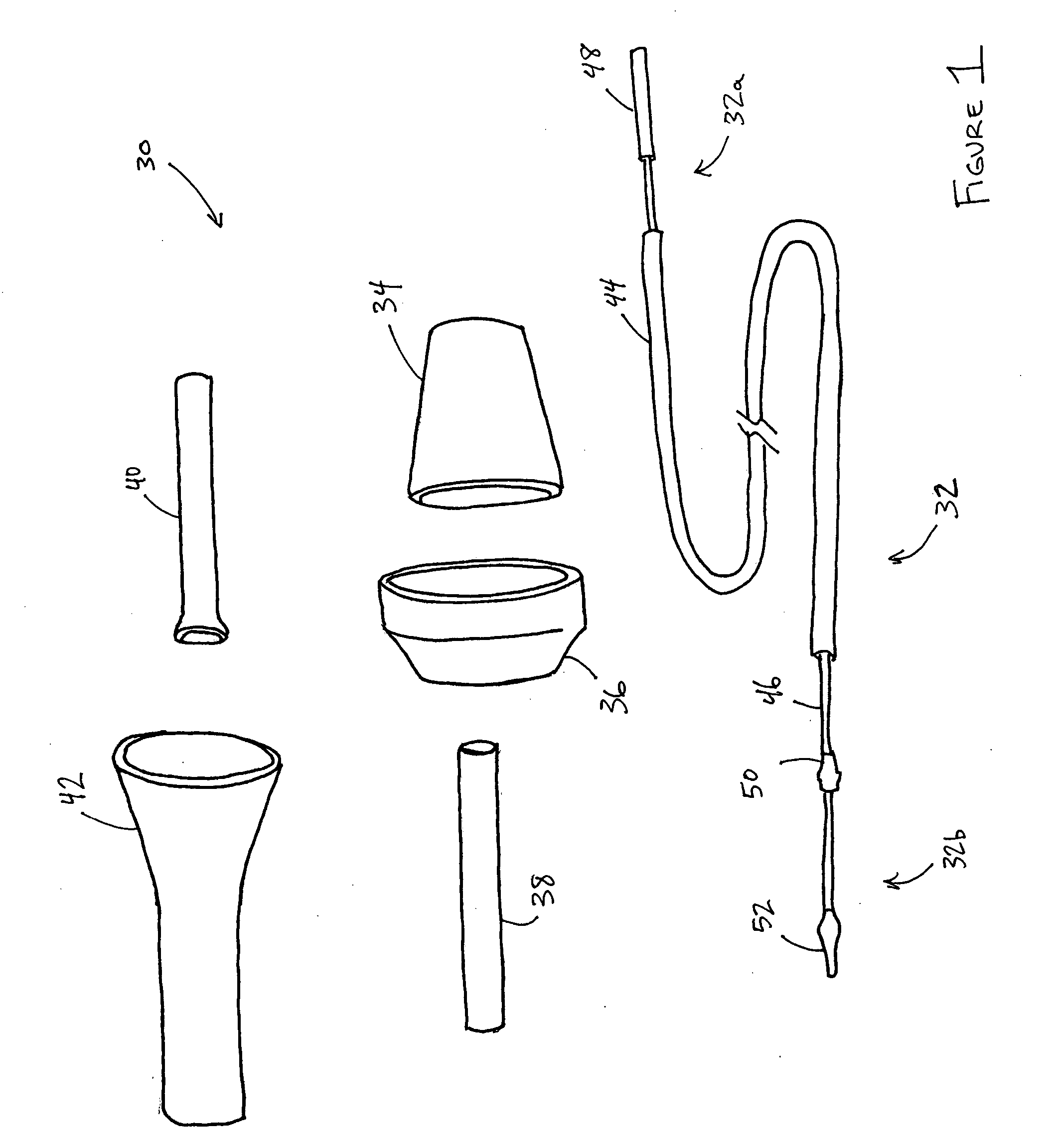
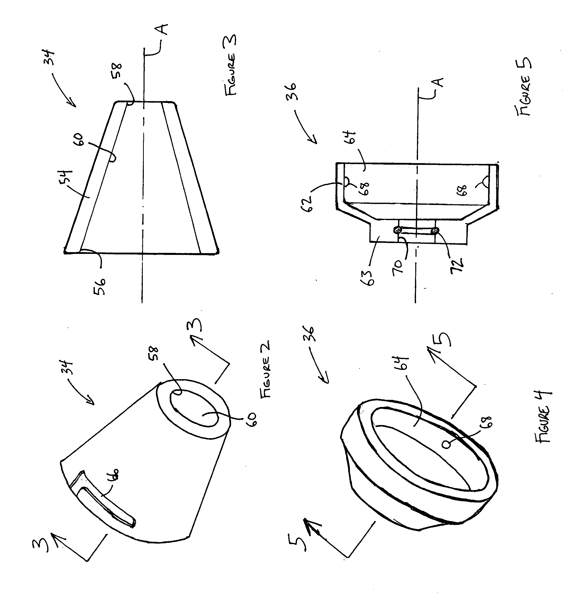
A system for loading a replacement valve prosthesis onto a minimally invasive delivery system, such as a delivery catheter. The system may include one or more frustoconical housings which define a tapered surface. The prosthesis may be moved along the tapered surface to compress the prosthesis. Desirably, for compression of the valve portion of the prosthesis, the prosthesis is moved along the tapered surface in a direction wherein the inlet end of the valve leads an outlet end of the valve. After compression, the prosthesis may be loaded into the sheath of the delivery catheter. Methods of loading the replacement valve prosthesis are also disclosed.

Description

RELATED APPLICATION [0001] This application is related to, and claims priority from, U.S. Provisional Patent Application No. 60 / 790,636, filed Apr. 10, 2006, the entirety of which is hereby incorporated by reference herein and made a part of the present disclosure.BACKGROUND OF THE INVENTION [0002] 1. Field of the Invention [0003] The present invention relates generally to a system and method for loading a prosthetic cardiac valve assembly onto a minimally invasive delivery system, such as a delivery catheter, for example. The invention may also be used to load other nonvalvular prosthetic frames onto a delivery system. [0004] 2. Description of the Related Art [0005] Currently, the replacement of a deficient cardiac valve is often performed by opening the thorax, placing the patient under extracorporeal circulation or peripheral aorto-venous heart assistance, temporarily stopping the heart, surgically opening the heart, excising the deficient valve, and then implanting a prosthetic ...

Claims


Application Information

Patent Timeline
IPC IPC(8): A61F2/24A61F2/84
CPCA61F2002/9522A61F2/2436A61F2/9522A61F2/9525
Inventor NGUYEN, THAN
Owner BAE SYST INFORMATION & ELECTRONICS SYST INTERGRATION INC
Learn More