
Kalman filter approach to processing electormacgnetic data

Inactive Publication Date: 2007-10-11
EXXONMOBIL UPSTREAM RES CO
View PDF10 Cites 28 Cited by
  • Summary
  • Abstract
  • Description
  • Claims
  • Application Information

AI Technical Summary

Benefits of technology

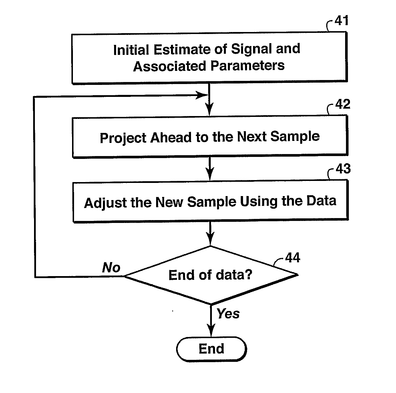
[0012] In some embodiments of the invention, the tracking algorithm is a Kalman algorithm, involving a state vector specified by a state equation and a measurement equation. In some of those embodiments, the state vector has two components, the signal's amplitude and the quadrature signal. In other embo

Problems solved by technology

These windows cannot be too large because signal amplitude and relative phase may change substantially within the analysis window.
Small windows, however, allow only minimal signal-to-noise ratio improvement.
Another problem with existing methods is that they don't take advantage of signal and noise correlations.
Low-frequency magnetotelluric (“MT”) noises, in particular, are a significant problem for active source marine EM imaging because they can masquerade as signal.
Other signal and noise correlations (e.g., signal correlations on the two horizontal components) are not optimally used in current approaches.

Method used


Image

  • Kalman filter approach to processing electormacgnetic data
  • Kalman filter approach to processing electormacgnetic data
  • Kalman filter approach to processing electormacgnetic data

Examples


example

[0050] An example with modeled horizontal electric dipole data is illustrated in FIGS. 5 to 10. FIG. 5 shows the modeled data with additive random noise. The signal frequency is 0.25 Hz and decays roughly exponentially away from the zero-time position. The additive noise is taken from recorded ambient magnetotelluric noise. FIG. 6 illustrates a blow-up of this noisy input data (initial signal plus additive noise) 61 at around 5000 seconds. Plotted on the same figure is the noise-free signal portion 62 of the model data and an estimate 63 of the signal made by using the method of the present invention. The estimate 63 is nearly equal to the noise-free signal 62, and difficult to distinguish from it in FIG. 6. This close similarity is a measure of the present inventive method's success, because the method does not “know” the model signal. It is given only the noisy data as input but is able to recover the signal portion. The embodiment of the present invention that was used in this ex...


PUM


Abstract

A method for tracking a sinusoidal electromagnetic signal in noisy data using a Kalman filter or other tracking algorithm. The method is useful for controlled source electromagnetic surveying where longer source-receiver offsets can cause the source signal to decay significantly and be difficult to retrieve from magnetotelluric or other electromagnetic background.

Description

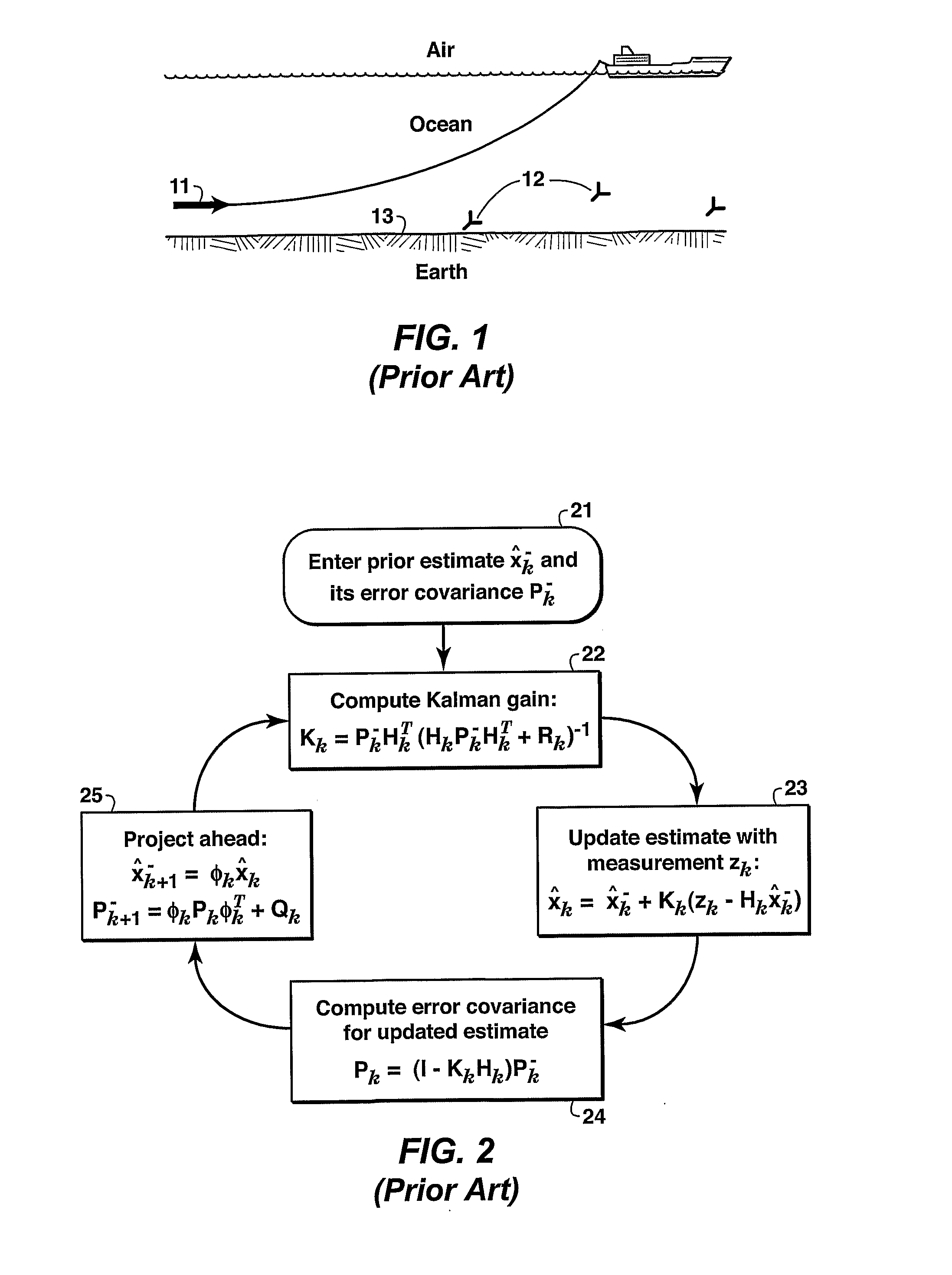
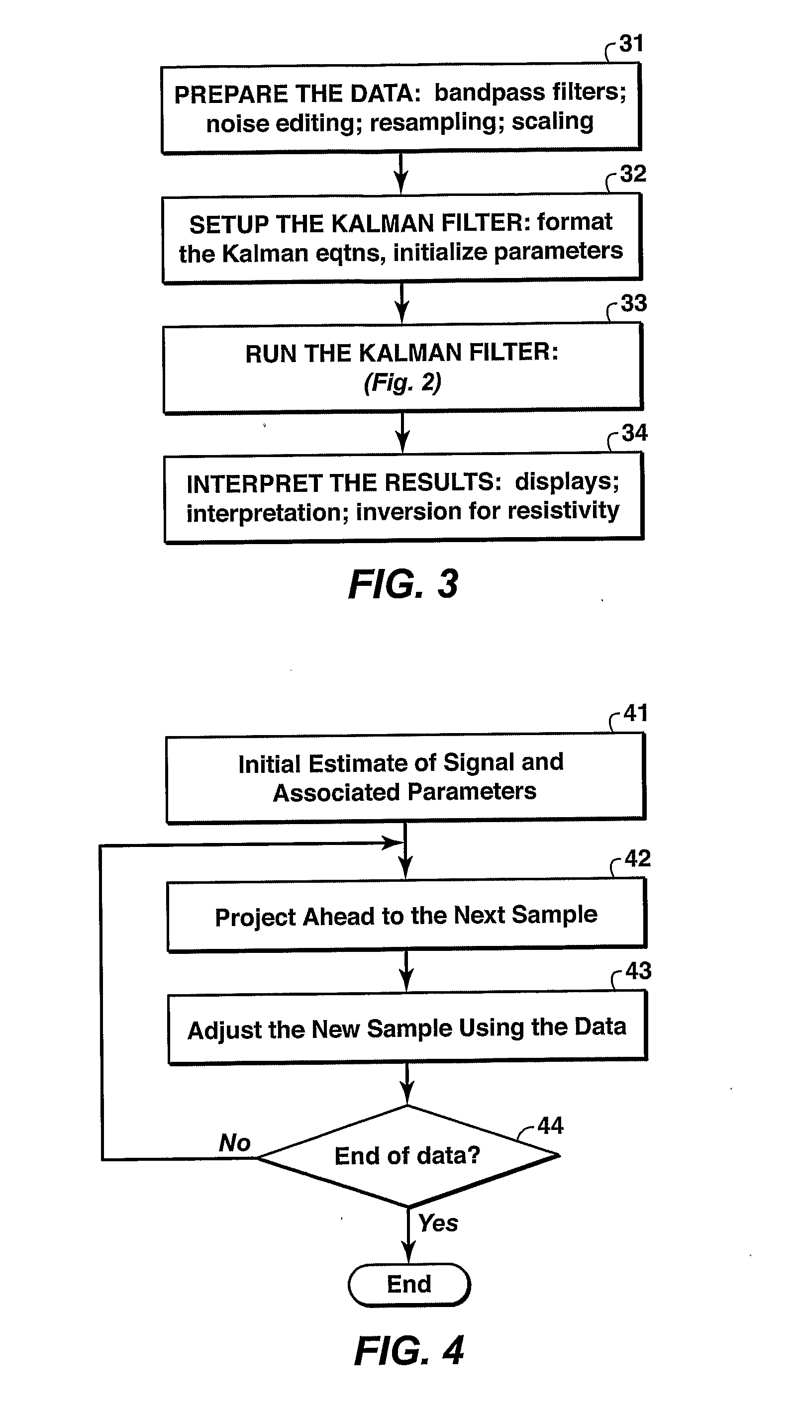
[0001] This application claims the benefit of U.S. Provisional Patent Application No. 60 / 576,201 filed on Jun. 1, 2004.FIELD OF THE INVENTION [0002] This invention relates generally to the field of geophysical prospecting and, more particularly, to electromagnetic methods used to explore for hydrocarbons. Specifically, the invention is a method for tracking electromagnetic source signals used in controlled source electromagnetic prospecting so that the signal can be recovered from noise. BACKGROUND OF THE INVENTION [0003] Controlled-source electromagnetic (“CSEM”) geophysical surveys use active (man-made) sources to generate electromagnetic fields to excite the earth, and deploy receiver instruments on the earth's surface, the seafloor, or inside boreholes to measure the resulting electric and magnetic fields, i.e., the earth's response to the source excitation. FIG. 1 illustrates the basic elements of an offshore CSEM survey. A vessel tows a submerged CSEM transmitter 11 over an ar...

Claims


Application Information

Patent Timeline
IPC IPC(8): G06F19/00G06F17/40G01V3/12
CPCG01V3/083G01V3/38G01V3/12
Inventor HORNBOSTEL, SCOTT
Owner EXXONMOBIL UPSTREAM RES CO
Learn More