
Testing of bottomhole samplers using acoustics

a sampler and bottomhole technology, applied in the field of hydrocarbon samples testing, can solve the problems of curtail production operations, asphaltenes tend to have a more complex chemical nature than wax and form, and subsequent disruption of the intermolecular balance needed

Active Publication Date: 2007-10-18
HALLIBURTON ENERGY SERVICES INC
View PDF26 Cites 28 Cited by
  • Summary
  • Abstract
  • Description
  • Claims
  • Application Information

AI Technical Summary

Benefits of technology

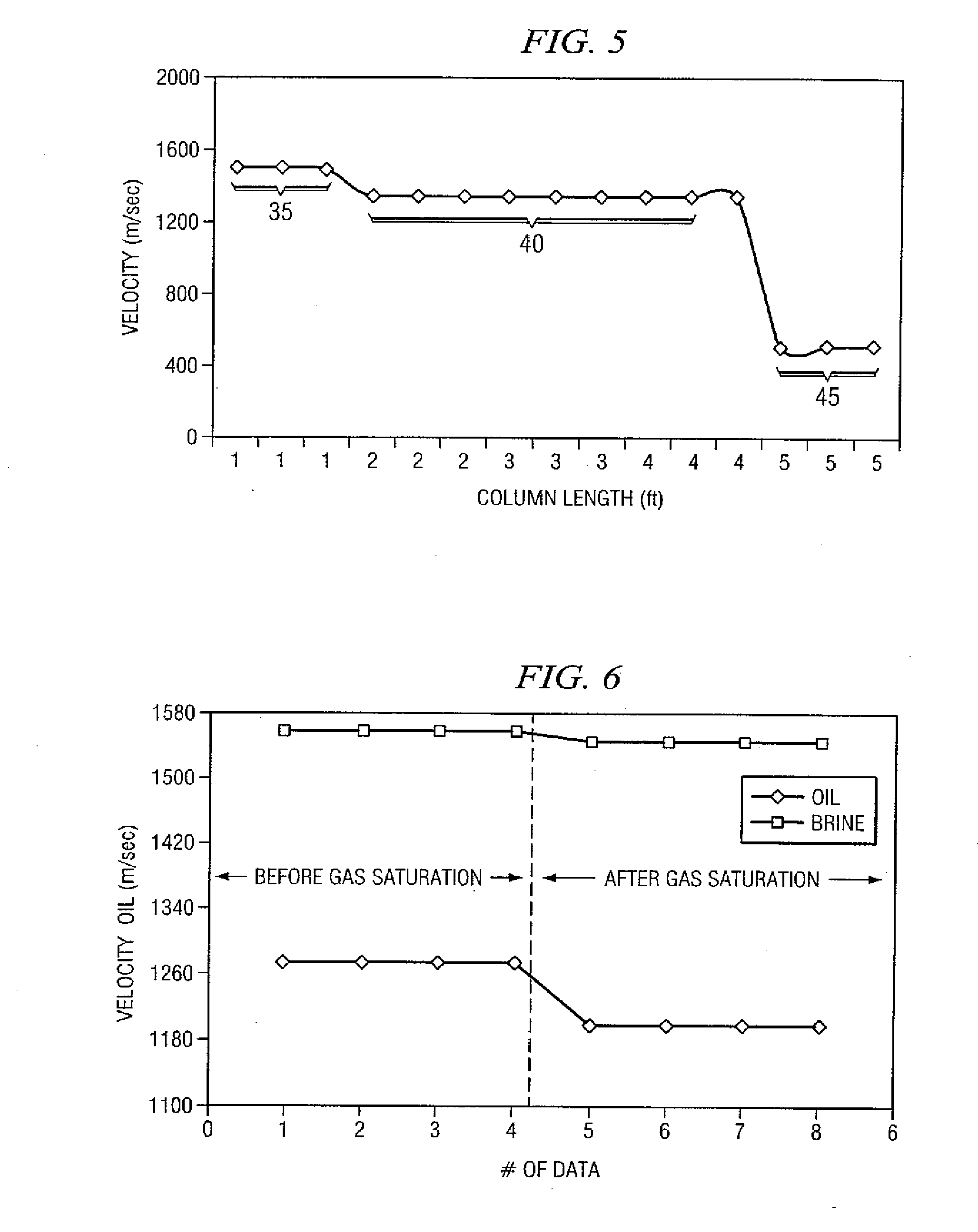
[0015] It will therefore be seen that a technical advantage of the present invention includes an apparatus and method for quickly and efficiently testing hydrocarbon bottomhole samples, thereby eliminating problems encountered by using conventional testing techniques. For instance, problems encountered with the delay and cost of sending samples to a laboratory are overcome. Other problems include not knowing certain information, such as knowing whether a sample was actually taken and knowing the quality of the sample, until the expense and time of sending the sample to the laboratory is undertaken. Such other problems are overcome by the present invention, which can readily determine information such as the location of the piston in the sample chamber and the presence and quantification of water, oil, and gas in the sample chamber. The location of the piston can indicate whether a sample was even collected, while the quantification of the remaining components provides information on the type and quality of the sample collected. The present invention allows this information to be generated on the drilling platform in real time as soon as the bottomhole samples have come to the surface. Such real time testing allows the operator to determine whether additional samples need to be taken and how elaborate the handling of the samples should be prior to additional testing. In addition, the present invention overcomes the problems of asphaltene precipitation with the conventional saturation pressure determination methods by detecting phase transitions substantially at the saturation pressure, which can avoid the asphaltene precipitation.
[0016] The foregoing has outlined rather broadly the features and technical advantages of the present invention in order that the

Problems solved by technology

Wax particles are high molecular weight paraffinic species that precipitate primarily due to temperature drop and can curtail production operations by agglomeration, sticking to pipe walls, congealing in flow lines, and the like.
Asphaltenes tend to have a more complex chemical nature than wax and form primarily due to a disruption in a fine balance of interactions that keep them in suspension / solution in the bulk crude.
Asphaltene precipitation is usually preceded by a drop in system pressure that leads to gas release and subsequent disruption of the inter-molecular balance needed to keep them stabilized.
Once formed, asphaltenes are typically at least as disruptive to flow operations as wax formation.
Drawbacks to the typical laboratory measurements include the time delay involved in laboratory testing and the costs involved with such a delay.
Costs for storing and transporting the samples for the laboratory testing can be significant.
In addition, the expense of collecting samples can be significant as well for most exploratory environments such as offshore or remote locations.
Other drawbacks include not knowing the quality of a sample or whether a sample was even collected until the expense and delay of laboratory testing has been conducted.
Drawbacks to such conventional methods include the system pressure typically having to be dropped significantly below the saturation pressure in order to define a clear transition point.
For some systems, a significant pressure drop below the saturation pressure may result in asphaltene precipitation taking place, which is very difficult to reverse.

Method used


Image

  • Testing of bottomhole samplers using acoustics
  • Testing of bottomhole samplers using acoustics
  • Testing of bottomhole samplers using acoustics

Examples


Embodiment Construction

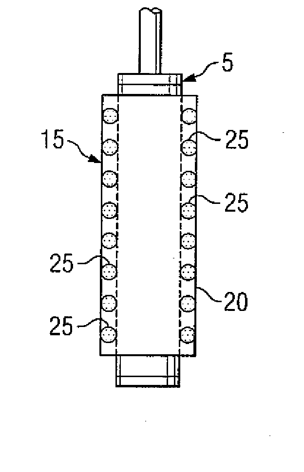
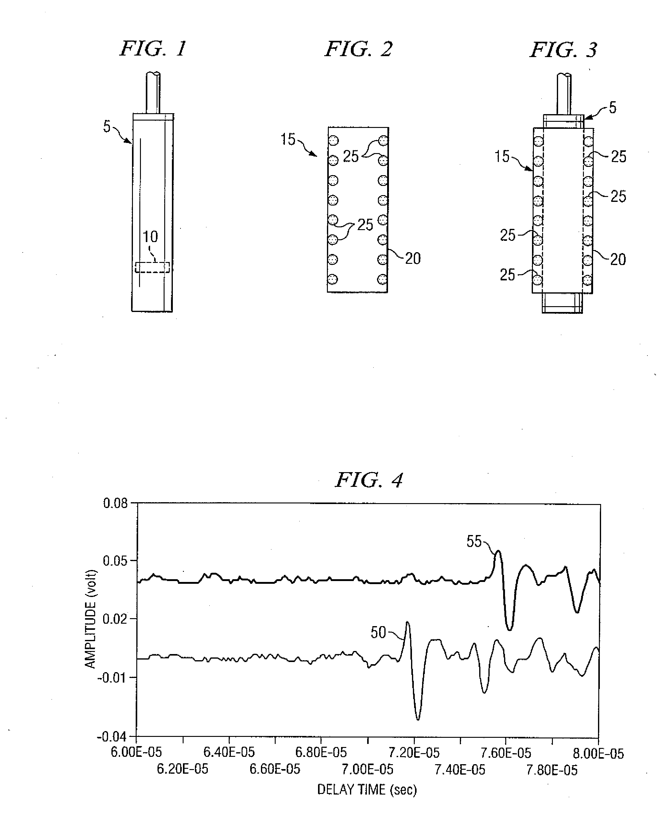
[0011] These and other needs in the art are addressed in one embodiment by a system for testing a fluid, wherein the fluid is disposed within a sample container. The system comprises at least one set of acoustic sensors, wherein the acoustic sensors are disposed about the sample container in a configuration comprising at least one configuration selected from the group consisting of radial and longitudinal, and wherein the at least one set of acoustic sensors generates at least one acoustic signal having a velocity through the fluid. The system farther comprises a means for recording and interpreting at least one acoustic signal generated by at least one set of acoustic sensors, wherein the velocity of the at least one acoustic signal indicates information about the fluid system.

[0012] In another embodiment, the present invention comprises an apparatus for testing a hydrocarbon sample. The apparatus comprises a sheath disposed about the hydrocarbon sample. In addition, the apparatus...


PUM

PropertyMeasurementUnit
frequencyaaaaaaaaaa
frequencyaaaaaaaaaa
frequencyaaaaaaaaaa

Abstract

A method for testing a hydrocarbon sample. In one embodiment, the apparatus comprises a sheath disposed about the hydrocarbon sample. The apparatus further comprises at least one set of acoustic sensors, wherein the at least one set of acoustic sensors is secured to the sheath, and further wherein at least one set of acoustic sensors produces an acoustic signal having a velocity through the hydrocarbon sample. In addition, the velocity is measured to provide information about the hydrocarbon sample. In other embodiments, the at least one set of acoustic sensors is disposed radially about the hydrocarbon sample.

Description

CROSS-REFERENCE TO RELATED APPLICATIONS [0001] This non-provisional application claims the benefit of U.S. Provisional Application No. 60 / 554,479, filed Mar. 19, 2004, which is hereby incorporated by reference in its entirety.STATEMENT REGARDING FEDERALLY SPONSORED RESEARCH OR DEVELOPMENT [0002] Not applicable.BACKGROUND OF THE INVENTION [0003] 1. Field of the Invention [0004] This invention relates to the field of testing fluid samples and more specifically to testing hydrocarbon samples using acoustic signals. [0005] 2. Background of the Invention [0006] There are pressing needs for inexpensive real time interpretation of hydrocarbon samples collected in bottom hole samplers. Typically, a hydrocarbon sample is collected from an underground reservoir primarily for establishing its pressure-volume-temperature (PVT) and flow assurance properties such as the onset of solids. [0007] PVT information about a hydrocarbon sample can include many different types of information. An important...

Claims


Application Information

Patent Timeline
Patent Type & Authority Applications(United States)
IPC IPC(8): G01V1/00E21BE21B47/00E21B49/08G01N29/02G01N29/024G01N29/22G01N33/28
CPCG01N29/024G01N29/222G01N33/28G01N2291/106G01N2291/02881G01N2291/048G01N2291/02872
Inventor IRANI, CYRUSHAKIMUDDIN, MUSTAFA
Owner HALLIBURTON ENERGY SERVICES INC
Learn More