
Throttle control apparatus and method for throttle control

a technology of throttle control and throttle body, which is applied in the direction of mechanical equipment, mechanical devices, operating means/release devices of valves, etc., can solve the problem that the response in full close control may become insufficient, and achieve the effect of reducing the moving speed of the valv

Inactive Publication Date: 2007-10-18
DENSO CORP
View PDF0 Cites 41 Cited by
  • Summary
  • Abstract
  • Description
  • Claims
  • Application Information

AI Technical Summary

Benefits of technology

[0010]According to another aspect of the present invention, a method for throttle control includes manipulating a valve toward a control target, which deviates from a full close position with respect to a close rotative direction. The method further includes reducing moving speed of the valve gradually toward the control target when the throttle position is a specific position in the vicinity of the full close position.

Problems solved by technology

As a result, response in the full close control may become insufficient.

Method used


Image

  • Throttle control apparatus and method for throttle control
  • Throttle control apparatus and method for throttle control
  • Throttle control apparatus and method for throttle control

Examples


first embodiment

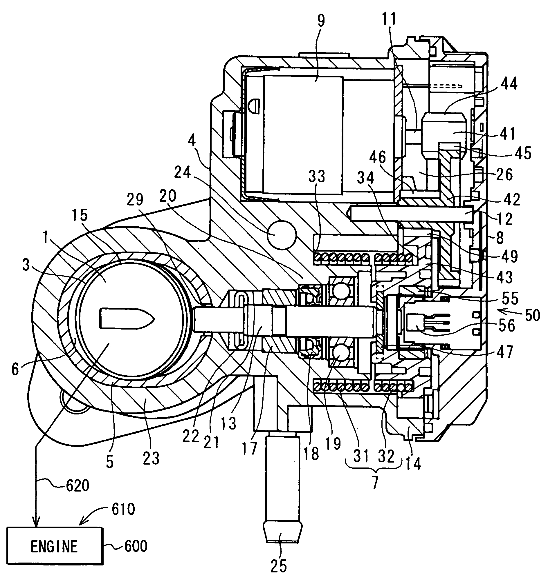
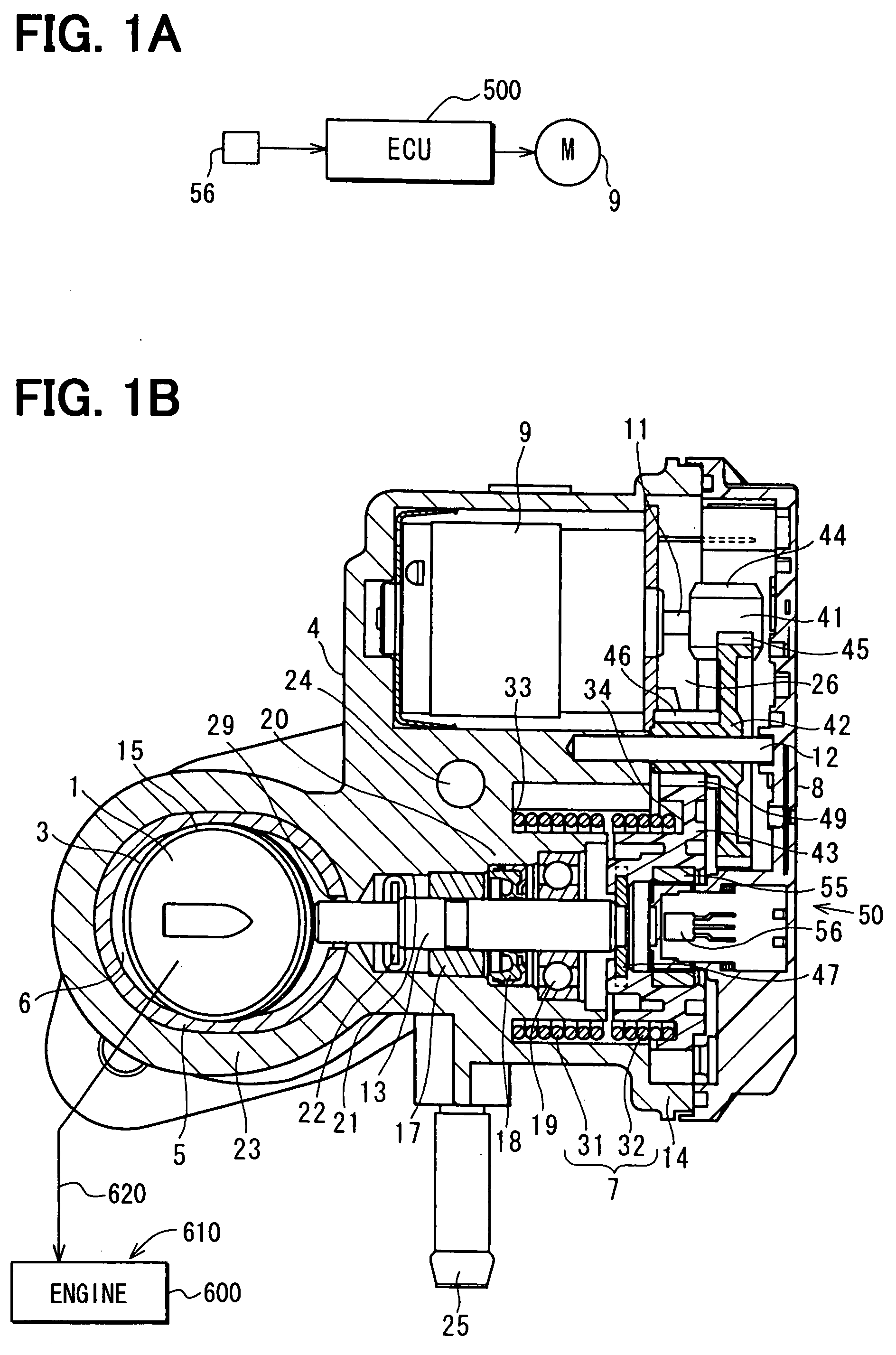
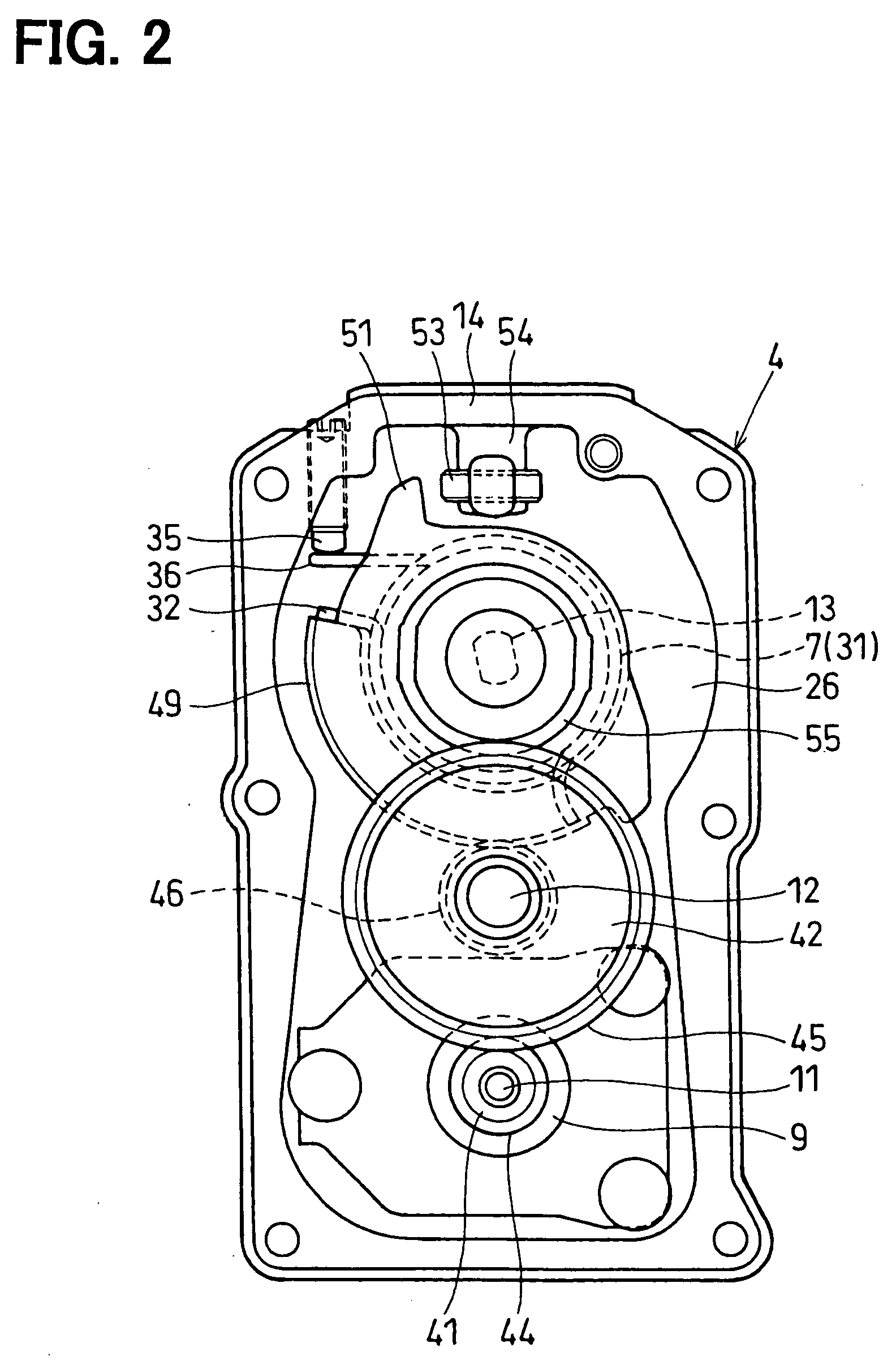
[0022]As shown in FIGS. 1A to 5, in this embodiment, an exhaust gas recirculation apparatus (EGR apparatus) is provided to an internal combustion engine 600 mounted in an engine room of a vehicle such as an automobile. The EGR apparatus includes an exhaust gas recirculation control valve (EGR valve) for controlling an amount of exhaust gas recirculated through an exhaust gas recirculation pipe (EGR pipe). The EGR apparatus further includes a throttle control apparatus for actuating a butterfly valve (valve member) 1 of the EGR valve.

[0023]The engine 600 is, for example, a direct-injection diesel engine, in which fuel is injected directly into combustion chambers 610. The engine 600 may be a turbocharged diesel engine. The engine 600 includes an intake pipe, an exhaust pipe, and a purification device. Intake air is supplied into each combustion chamber 610 of each cylinder of the engine 600 through the intake pipe. Exhaust gas is discharged from the combustion chamber 610 to the outs...

second embodiment

[0098]In this embodiment, as shown in FIG. 6, the ECU 500 primarily sets the control target of the butterfly valve 1 at the dead band minimum position (DBMIN) in the full close control of the butterfly valve 1 during the engine operation. Subsequently, the ECU 500 changes the control target of the butterfly valve 1 to the full close control point (A) at the moment where the ECU 500 detects that the throttle position, which is detected using the EGR sensor 50, passes by the full close control point (A, θ=0°) with respect to the close rotative direction (CL).

[0099]In an initial condition of the full close control of the butterfly valve 1 during the engine operation, the ECU 500 performs the accelerating control so as to gradually accelerate operating speed of the butterfly valve 1 toward the dead band minimum position (DBMIN). In an intermediate condition of the full close control of the butterfly valve 1 during the engine operation, the ECU 500 performs the constant control so as to ...

third embodiment

[0104]In this embodiment, as shown in FIG. 7, the ECU 500 primarily sets the control target of the butterfly valve 1 at the dead band minimum position (DBMIN) in the full close control of the butterfly valve 1 during the engine operation. Subsequently, the ECU 500 changes the control target of the butterfly valve 1 to the dead band maximum position (DBMAX) at the moment where the ECU 500 detects that the throttle position, which is detected using the EGR sensor 50, passes by the full close control point (A, θ=0°) with respect to the close rotative direction (CL).

[0105]In an initial condition of the full close control of the butterfly valve 1 during the engine operation, the ECU 500 performs the accelerating control so as to gradually accelerate operating speed of the butterfly valve 1 toward the dead band minimum position (DBMIN). In an intermediate condition of the full close control of the butterfly valve 1 during the engine operation, the ECU 500 performs the constant control so ...


PUM


Abstract

A throttle control apparatus includes a housing defining therein a fluid passage. A motor is provided for generating driving force to rotate a valve. The valve blocks the fluid passage when the valve is in a full close position. A throttle position detecting unit detects a throttle position of the valve. A control unit is adapted to performing a full close control to manipulate the valve toward a control target by setting the control target at a throttle position deviating from the full close position in a close rotative direction. The control unit starts a deceleration control to reduce moving speed of the valve gradually toward the control target in the full close control when the throttle position is a specific position in the vicinity of the full close position.

Description

CROSS REFERENCE TO RELATED APPLICATIONS[0001]This application is based on and incorporates herein by reference Japanese Patent Application No. 2006-111747 filed on Apr. 14, 2006.FIELD OF THE INVENTION[0002]The present invention relates to a throttle control apparatus. The present invention further relates to a method for a throttle control.BACKGROUND OF THE INVENTION[0003]Conventionally, a throttle control apparatus includes a motor control unit for controlling electricity supplied to an electric motor to manipulate a valve member of a fluid control valve. According to EP 1426589 A2 (JP-A-2004-169614), an exhaust gas recirculation apparatus (EGR apparatus) is disclosed as an example of a fluid control valve. An internal combustion engine discharges exhaust gas from a combustion chamber thereof, and the EGR apparatus recirculates the exhaust gas as EGR gas partially into an air intake pipe of the engine. An exhaust gas recirculation valve (EGR valve) is provided midway through an exh...

Claims


Application Information

Patent Timeline
IPC IPC(8): F02D9/08F02D11/10F16K1/22
CPCF02M25/0756F02M25/0773F02M25/0793F16K31/042F16K1/221Y02T10/121F02M25/0795F02M26/48F02M26/54F02M26/70F02M26/73
Inventor SASAKI, KAZUSHI
Owner DENSO CORP
Features
  • Generate Ideas
  • Intellectual Property
  • Life Sciences
  • Materials
  • Tech Scout
  • Unparalleled Data Quality
  • Higher Quality Content
  • 60% Fewer Hallucinations
Learn More