Solar cells using arrays of optical rectennas

a solar cell and array technology, applied in the direction of semiconductor devices, electrical devices, nanotechnology, etc., can solve the problem that no substantial progress in practice has been reported

Inactive Publication Date: 2007-10-18
TRUSTEES OF BOSTON COLLEGE THE
View PDF102 Cites 144 Cited by
  • Summary
  • Abstract
  • Description
  • Claims
  • Application Information

AI Technical Summary

Problems solved by technology

To date, however, no substantial progresses in practice have been reported due to

Method used


Image

  • Solar cells using arrays of optical rectennas
  • Solar cells using arrays of optical rectennas
  • Solar cells using arrays of optical rectennas

Examples


example 1

[0063] With this example, optical measurements of random arrays of aligned carbon nanotubes are disclosed, and show that the response is consistent with conventional radio antenna theory. The example first demonstrates the polarization effect, the suppression of the reflected signal when the electric field of the incoming radiation is polarized perpendicular to the nanotube axis. Next, the example demonstrates the interference colors of the reflected light from an array, and show that they result from the length matching antenna effect. This antenna effect could be used in a variety of optoelectronic devices, including THz and IR detectors.

[0064] In recent years, periodic and random arrays of multi-walled carbon nanotubes (MWCNTs) have been synthesized on various substrates, by the plasma-enhanced chemical vapor deposition (PECVD) process. Each nanotube in such arrays is a metallic rod of about 50 nm in diameter and about 200 to about 1000 nm in length. Therefore, one can view inte...


PUM


Abstract

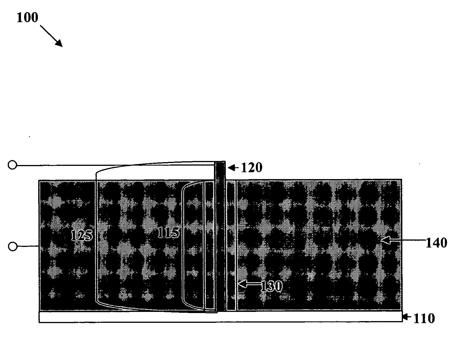
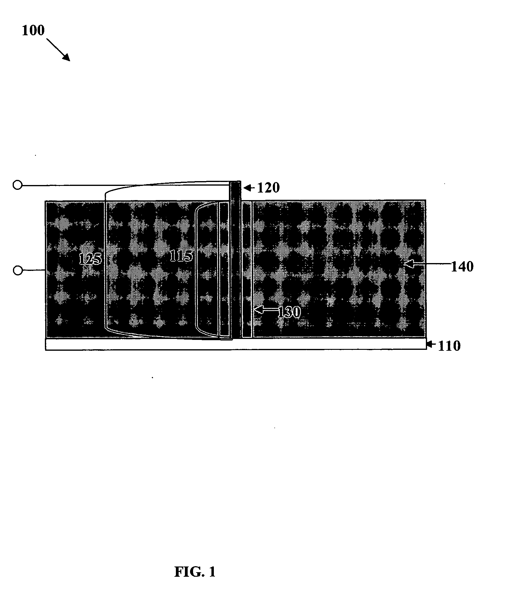
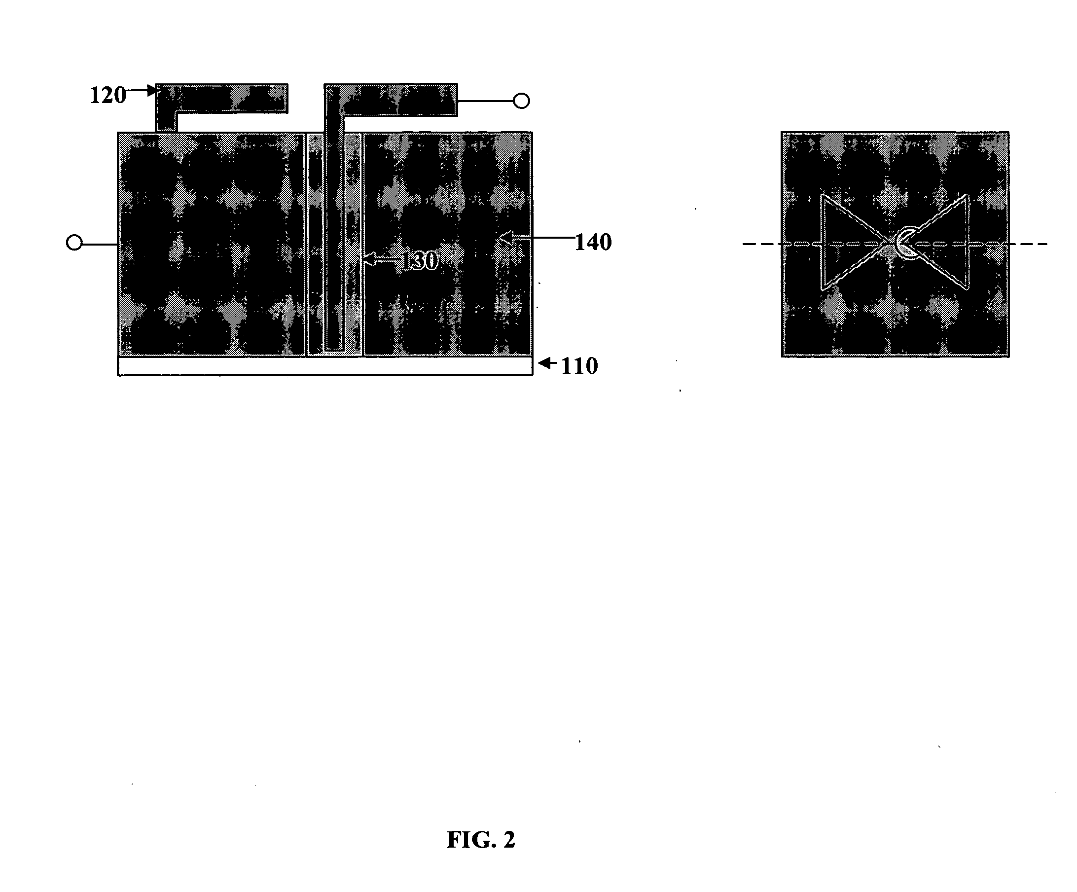
The present invention discloses a solar cell comprising a nanostructure array capable of accepting energy and producing electricity. In an embodiment, the solar cell comprises an at least one optical antenna having a geometric morphology capable of accepting energy. In addition, the cell comprises a rectifier having the optical antenna at a first end and engaging a substrate at a second end wherein the rectifier comprises the optical antenna engaged to a rectifying material (such as, a semiconductor). In addition, an embodiment of the solar cell comprises a metal layer wherein the metal layer surrounds a length of the rectifier, wherein the optical antenna accepts energy and converts the energy from AC to DC along the rectifier. Further, the invention provides various methods of efficiently and reliably producing such solar cells.

Description

RELATED APPLICATIONS [0001] This application claims the benefit of U.S. Provisional Application Ser. No. 60 / 619,262, filed Oct. 15, 2004, the entirety of which is hereby incorporated herein by reference.GOVERNMENT SUPPORT [0002] The present invention was made with partial support from The US Army Natick Soldier Systems Center under Grant Number DAAD16-02-C-0037 and partly by NSF under the grant NIRT 0304506. The United States Government retains certain rights to the invention.FIELD OF INVENTION [0003] The embodiments disclosed herein relate to nanoscale energy conversion devices having optical rectennas, and more particularly to high-efficiency solar cells having arrays of optical rectennas capable of receiving and transmitting solar energy and converting the solar energy into direct current electricity. BACKGROUND OF THE INVENTION [0004] The concept of using a rectifying antenna (rectenna) to collect solar energy was first proposed by R. L. Bailey in 1972; Since then, different app...

Claims


Application Information

Patent Timeline
IPC IPC(8): H01L31/00
CPCB82Y20/00H01L31/18H01L31/0352H01L31/035227H01L31/1085
Inventor REN, ZHIFENGKEMPA, KRZYSZTOFWANG, YANG
Owner TRUSTEES OF BOSTON COLLEGE THE
Why Eureka
Try Eureka