Double-sided solar module

Inactive Publication Date: 2007-10-18
SPARTZ THOMAS
View PDF37 Cites 18 Cited by
  • Summary
  • Abstract
  • Description
  • Claims
  • Application Information

AI Technical Summary

Benefits of technology

[0008] To address these concerns, an improved solar energy collector is provided which significantly increases collection efficiency. By orienting the collector surfaces in back-to-back fashion, a greater amount of light is collected. More specifically, a solar module for converting light into electric cu

Problems solved by technology

The intermittent power delivery of solar electricity is a primary drawback to widespread acceptance as a reliable source or part of an electrical grid transmission network.
Another limitation is that any portion of a conventional solar module not facing the light source is wasted.
Yet another obstacle to the acceptance of solar energy is performance per square meter.
Despite the many benefits of solar energy as a renewable distributed energy solution, when compared to other forms of electricity generation per kWh per square meter, solar energy is barely competitive.
Without greater performance per square meter, solar technology will not become an economically viable factor for electricity generation.
Photovoltaic modules manufactured using glass as a substrate, a superstrate, or as both surfaces have a high weight per unit area and are very fragile.
Although large solar collector modules can be desirable for corresponding greater electrical output, large modules are heavier, bulkier and more cumbersome.
However,

Method used


Image

  • Double-sided solar module
  • Double-sided solar module
  • Double-sided solar module

Examples


Embodiment Construction

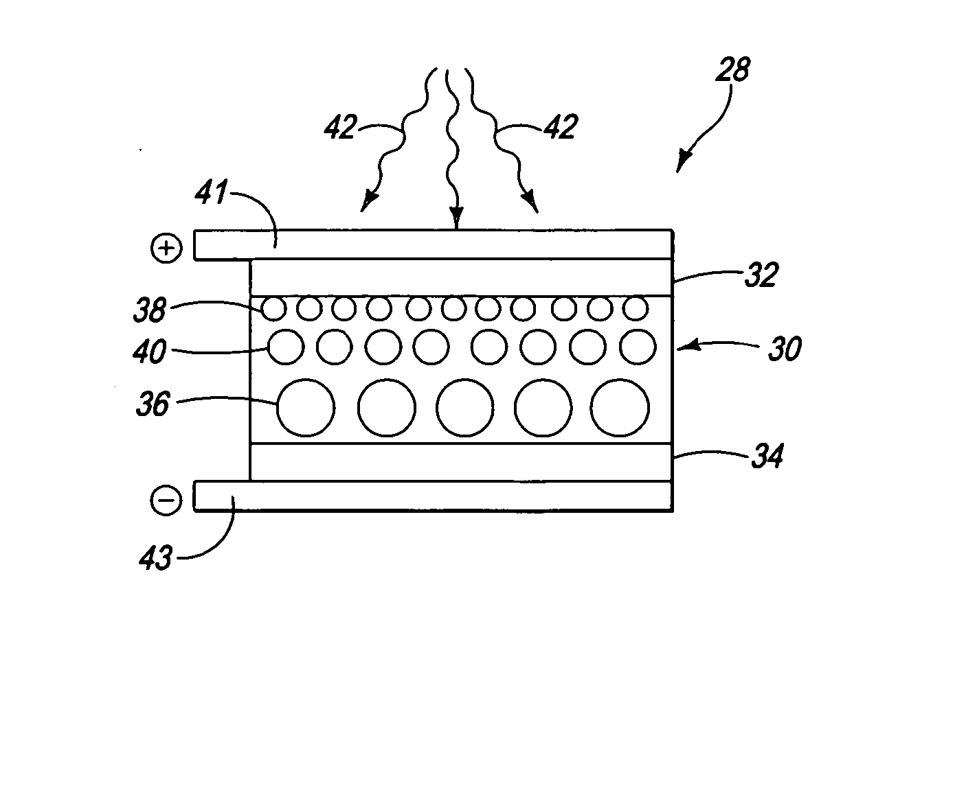
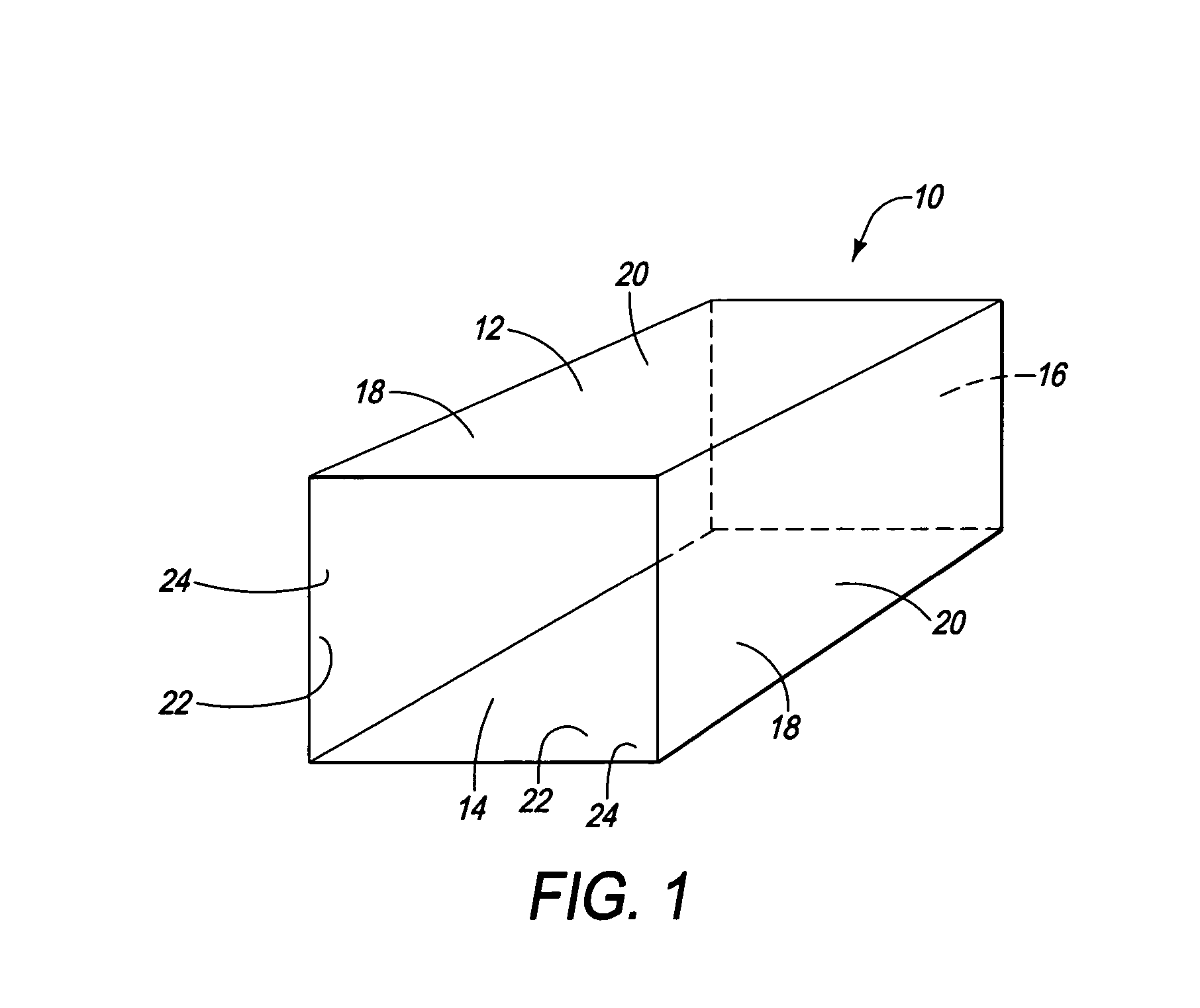
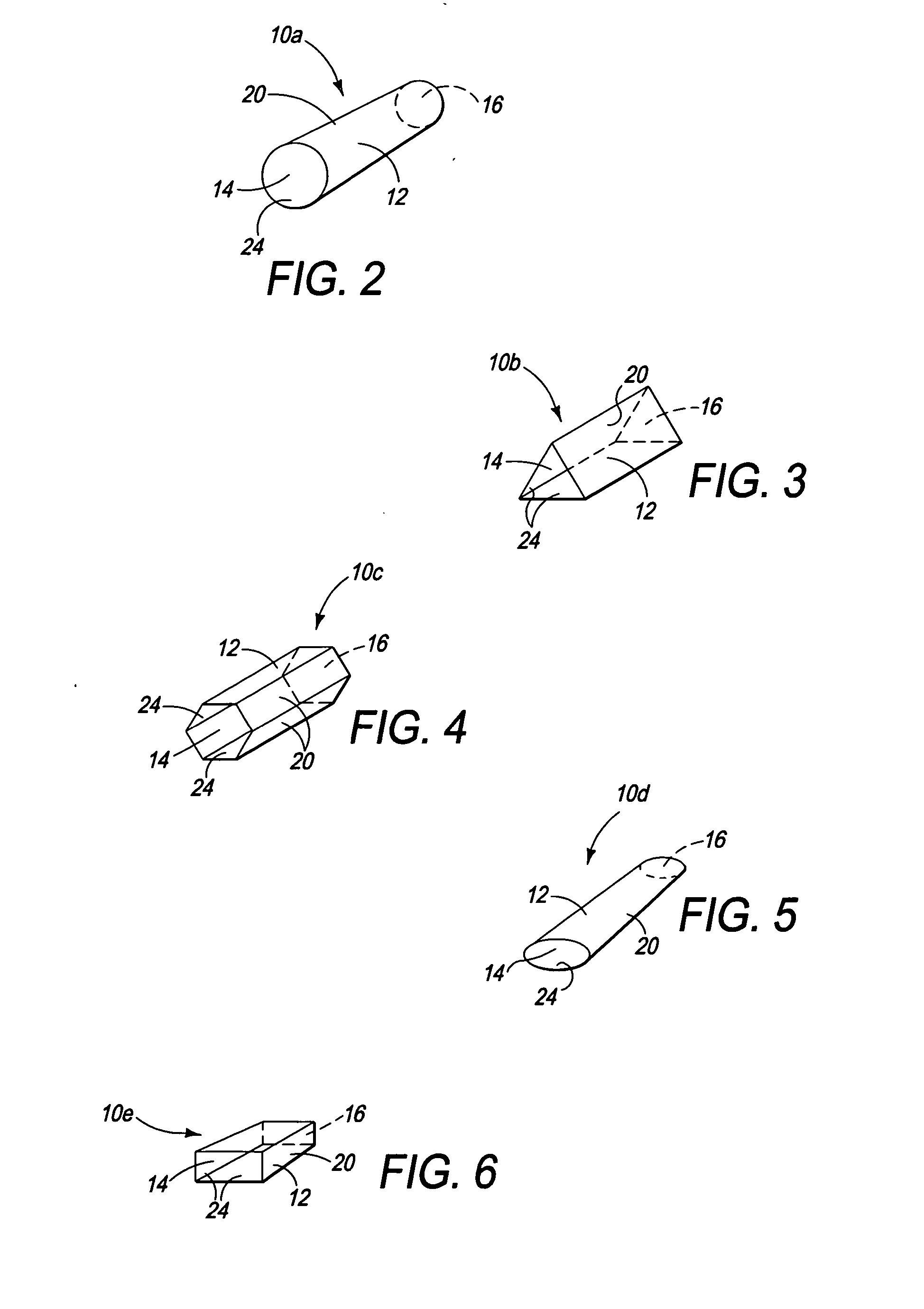
[0021] Turning now to FIG. 1, a solar module 10 in accordance with one embodiment of the present module includes a tubular body 12 and a pair of openings 14 and 16 at the opposite ends of the body. The two openings 14, 16 preferably have substantially the same dimensions, however variations are contemplated. An outside wall 18 of the body 12 is covered with a layer of thin film photovoltaic (TFPV) panel 20, which is oriented to have its light collecting surface facing out. Similarly, an inside wall 22 of the body 12 is also provided with a TFPV layer 24. The TFPV layers 20, 24 absorb visible, ultraviolet (UV) and infrared (IR) light from the sun or artificial light sources, and generates electric current.

[0022] Generally, the amount of electric current generated by the solar module 10 is dependent on the relationship between the lengths of the tubular body 12 and the width or area of the openings 14, 16. Deeper or longer length-to-opening ratios (e.g., 2 to 1) are less efficient pe...


PUM


Abstract

A solar module for converting light into electric current includes a hollow body having a first opening for enabling light to enter the hollow body. The module further includes an inside wall and an outside wall, and at least one photoactive layer for absorbing light attached to each wall for absorbing light and converting it into electric current.

Description

FIELD OF INVENTION [0001] The present invention relates generally to photovoltaic systems for converting light to electrical power, and more particularly to devices for increasing the efficiency and reliability of solar energy collection. BACKGROUND OF THE INVENTION [0002] The predominant type of solar modules built today is silicon-based, oriented for maximum exposure to light, and effective only when the light source is not obstructed through shade, cloudy or dirty conditions, which reduce the average power output to typically only a few production hours per day in the more populated areas around the world. The intermittent power delivery of solar electricity is a primary drawback to widespread acceptance as a reliable source or part of an electrical grid transmission network. Another limitation is that any portion of a conventional solar module not facing the light source is wasted. [0003] Yet another obstacle to the acceptance of solar energy is performance per square meter. Des...

Claims


Application Information

Patent Timeline
IPC IPC(8): H01L31/00
CPCB82Y20/00H01L31/035272H01L31/072H02S40/32H01L31/0735Y02E10/50H01L31/073
Inventor SPARTZ, THOMAS
Owner SPARTZ THOMAS
Why Eureka
Try Eureka