Perforated composites for joining of metallic and composite materials

a composite material and perforated technology, applied in the field of structural joints, can solve the problems of inability to meet the requirements of quality assurance, difficulty in ensuring the quality of the jointing method, so as to increase the load carrying capacity of the in-situ shaped fastener

Active Publication Date: 2007-10-18
LOCKHEED MARTIN CORP
View PDF12 Cites 74 Cited by
  • Summary
  • Abstract
  • Description
  • Claims
  • Application Information

AI Technical Summary

Benefits of technology

[0007] Embodiments in the present invention provide a system and method of joining structural members. This method involves aligning the first structural member to a metallic substrate when the first structural member has at least one shaped or tapered cavity. A metallic or other like material suited to cold spraying technology is deposited into the tapered cavity to form a shaped or tapered fastener bonded to the metallic substrate. The shape of the fastener, which is determined by the shape of the cavity, secures the first structural member to the metallic substrate. Additionally, a protective insert may be placed within the shaped or tapered cavity to protect the first structural member during the cold spraying deposition. The first structural member may be a composite material or other like material susceptible to erosion during the cold spraying technique. After the material has been deposited using cold spray techniques this material may be further solidified and bonded to the metallic substrate using a technique such as friction stir welding in order to increase the load carrying capacity of the in-situ shaped fastener.

Problems solved by technology

This joining method also requires significant setup time in drilling holes and installing fasteners to attach the members to one another.
Such holes often produce localized stresses and mechanical loads that the structure must account for.
Furthermore, quality assurance issues may arise when installing such fasteners (misdrilled holes and improper fastener installation is common).
However, smaller complex three dimensional structures, such as aircraft designs, have not been easily addressed by the application of FSW.
Thus it has been difficult to apply FSW processing to complex three-dimensional structures that involve both composites and metals.

Method used


Image

  • Perforated composites for joining of metallic and composite materials
  • Perforated composites for joining of metallic and composite materials
  • Perforated composites for joining of metallic and composite materials

Examples


Embodiment Construction

[0019] Embodiments of the present invention are illustrated in the FIGURES, like numerals being used to refer to like and corresponding parts of the various drawings.

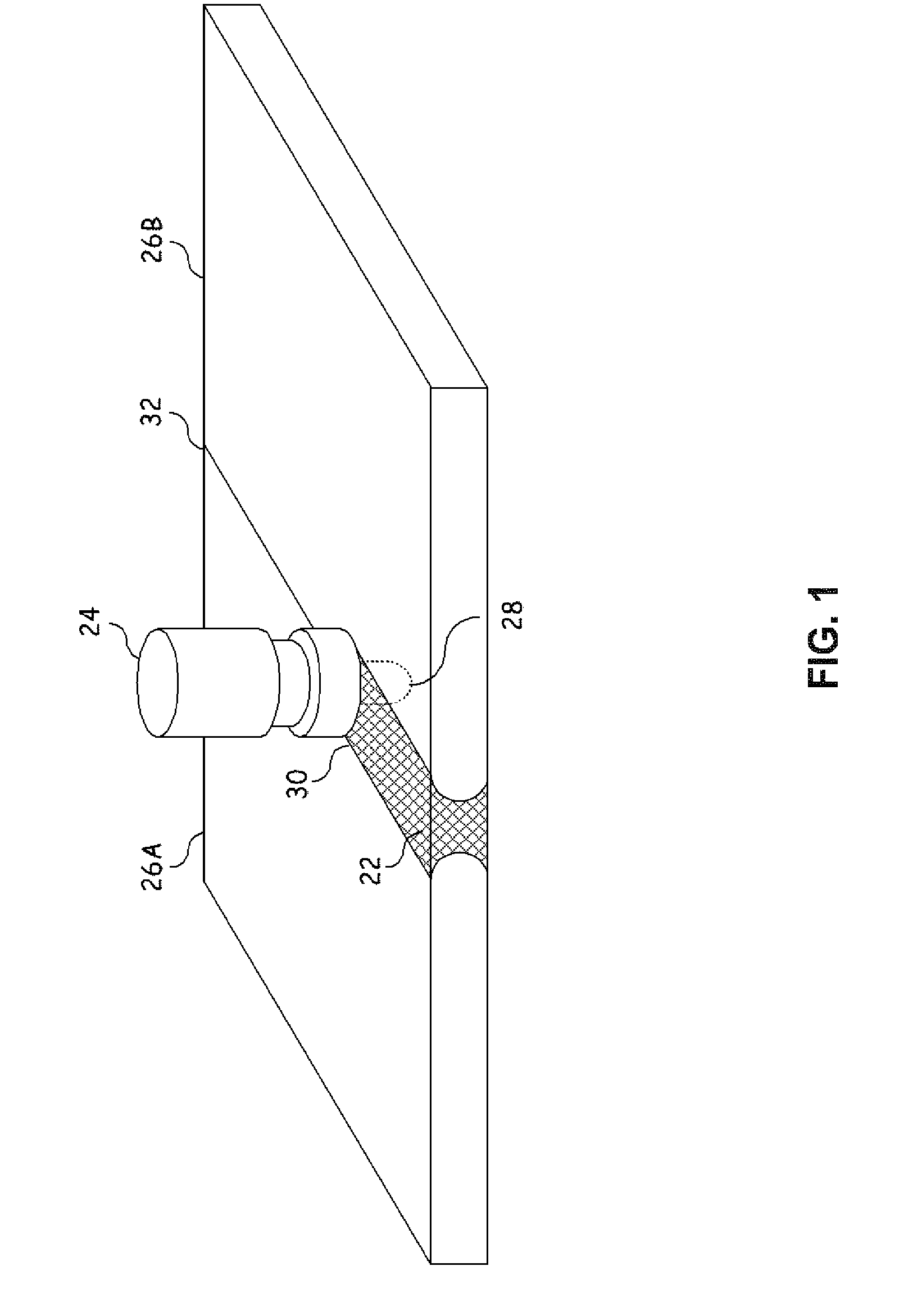
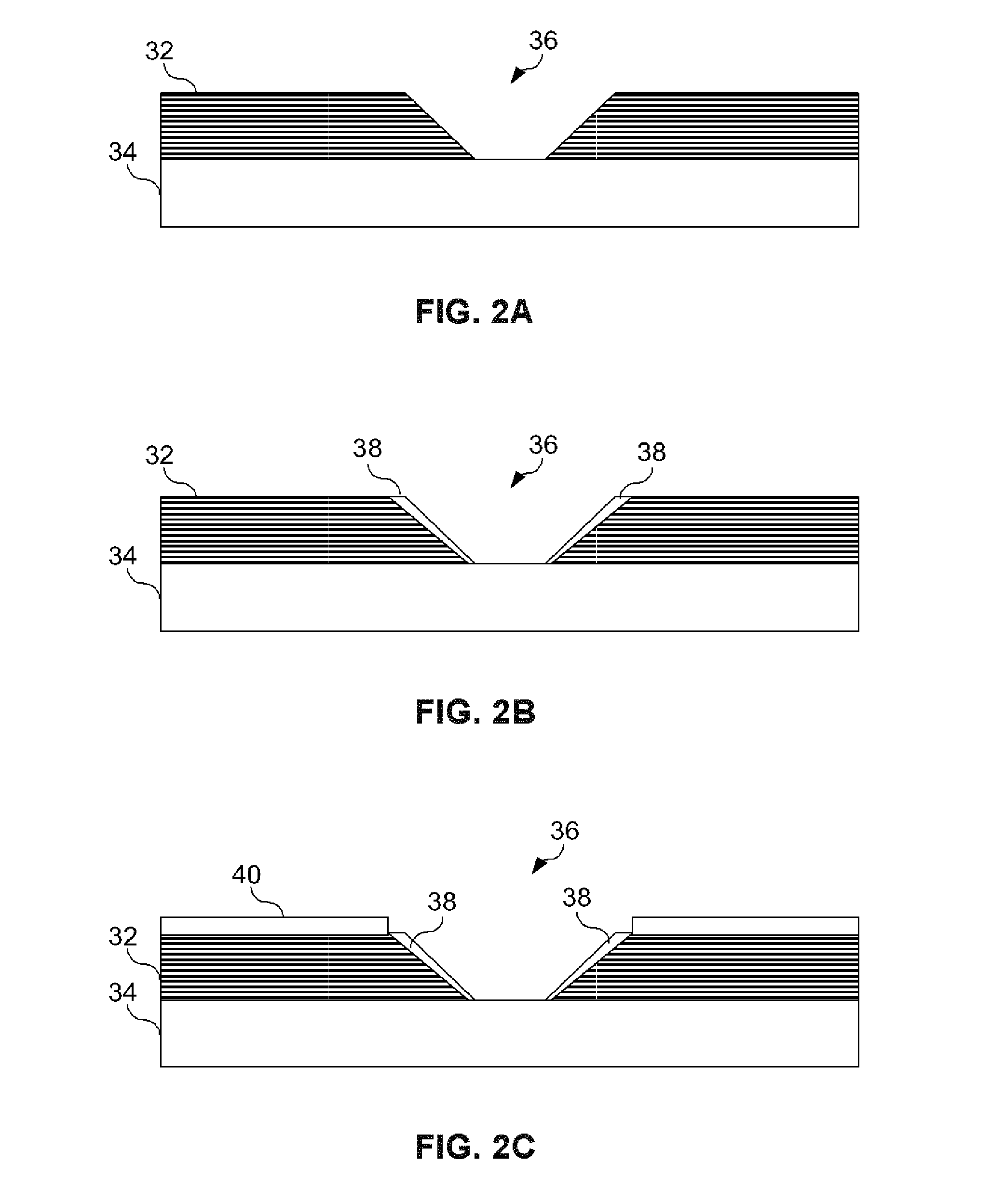
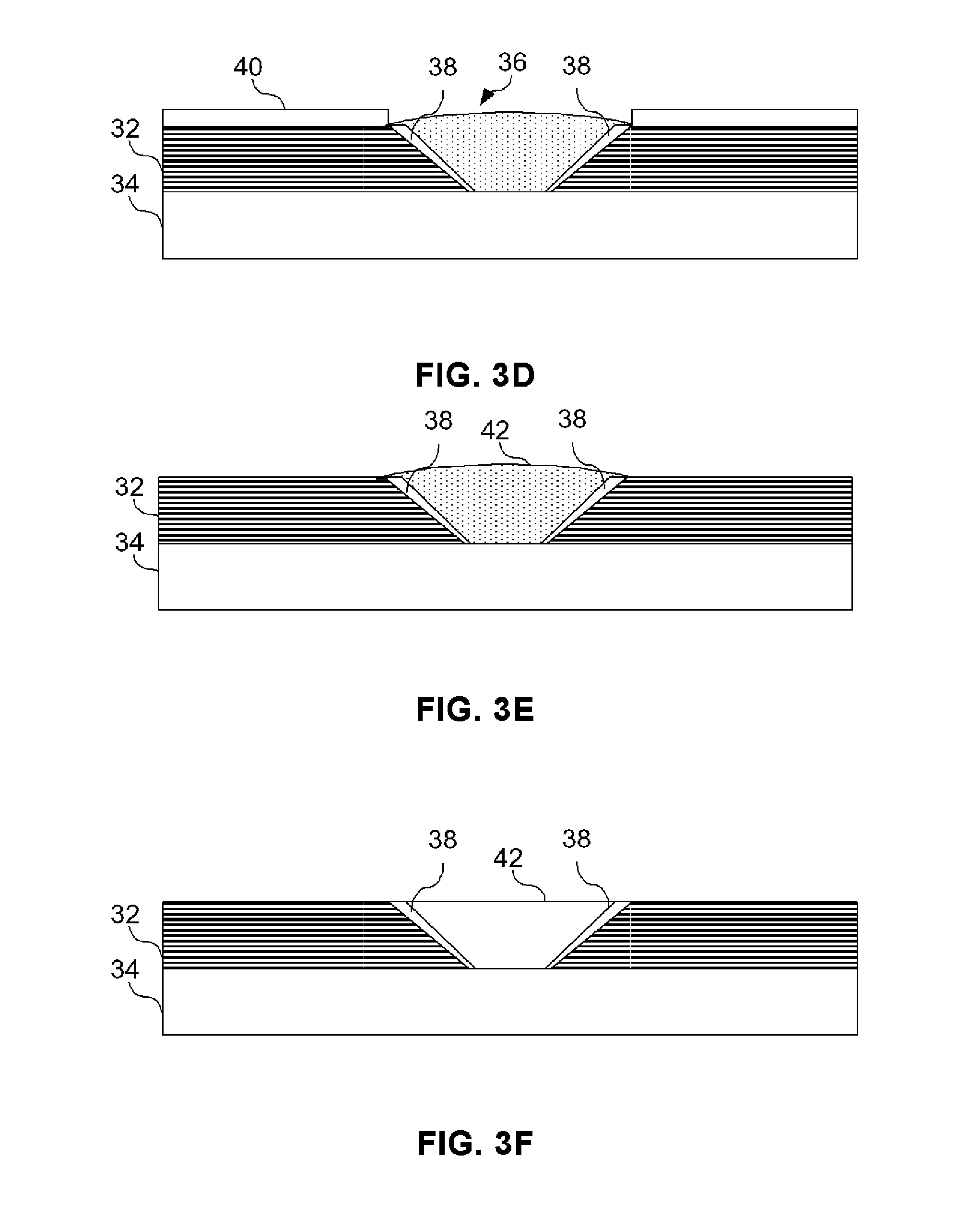
[0020] Embodiments in the present invention provide a system and method of joining structural members. This method involves aligning the first structural member to a metallic substrate wherein the first structural member has at least one shaped or tapered cavity. A metallic or other like material suitable to be deposited using cold spraying technology is placed in the tapered cavity to form an in-situ shaped or tapered fastener that is bonded to the metallic substrate. Cold spray technology (also referred to as kinetic metallization) is a metal deposition process in which a powder alloy is entrained in a gas stream traveling at near supersonic speeds. The high speed impact of the powder particle upon a surface results in a high degree of deformation in the particle and leads to a combination metallurgical and mechanica...


PUM

PropertyMeasurementUnit
stand-off distancesaaaaaaaaaa
metallicaaaaaaaaaa
weightaaaaaaaaaa

Abstract

Embodiments in the present invention provide a system and method of joining structural members. This method involves aligning the first structural member to a metallic substrate when the first structural member has at least one tapered hole or cavity. A metallic or other like material suitable to cold spraying technology is deposited into the tapered cavity to form a shaped or tapered fastener bonded to the metallic substrate. The shape of the fastener secures the first structural member to the metallic substrate. Additionally, a protective insert may be placed within the shaped or tapered cavity to protect the first structural member during hoe cold spraying deposition when the first structural member is a composite material or other like material susceptible to erosion during the cold spraying technique. After the material has been deposited using cold spray techniques this material may be further solidified and bonded to the metallic substrate using a technique such as friction stir welding in order to increase the load carrying capacity of the in-situ shaped fastener.

Description

TECHNICAL FIELD OF THE INVENTION [0001] The present invention relates generally to structural joints and more particularly a method to join two or more members. BACKGROUND OF THE INVENTION [0002] Structural joints in aircraft applications frequently involve the joining of metallic and composite structures. These joints are accomplished using typical fastening concepts which suffer from significant strength reductions caused by the need to drill holes in the metallic member. This joining method also requires significant setup time in drilling holes and installing fasteners to attach the members to one another. Such holes often produce localized stresses and mechanical loads that the structure must account for. To account for such localized loads, the structures are typically reinforced resulting in increased weight and loads to be handled by the structure. Furthermore, quality assurance issues may arise when installing such fasteners (misdrilled holes and improper fastener installati...

Claims


Application Information

Patent Timeline
Patent Type & Authority Applications(United States)
IPC IPC(8): A47J36/02
CPCB23K20/1225B23K20/1275C23C24/04C08J9/146C08J9/0023C08J9/122C08F112/08C08J9/0028
Inventor BARNES, JOHN E.KOON, ROBERT W.OLLIFFE, ROBERT J.ENGELSTAD, STEPHEN P.
Owner LOCKHEED MARTIN CORP
Why Eureka
Try Eureka