
Group wiring system allowing locating of wire pairs and method for locating wire pairs in group wiring system

Active Publication Date: 2007-10-18
WUXI UNIVERSAL NETWORK CORP
View PDF8 Cites 8 Cited by
  • Summary
  • Abstract
  • Description
  • Claims
  • Application Information

AI Technical Summary

Benefits of technology

[0005] An objective of the present invention is to provide a group wiring system that allows locating of wire pairs while a server system is on-line.
[0007] Detachment of the server system before the procedure for locating the wire pairs is not required. The operational efficiency is improved, and the labor and time are saved.
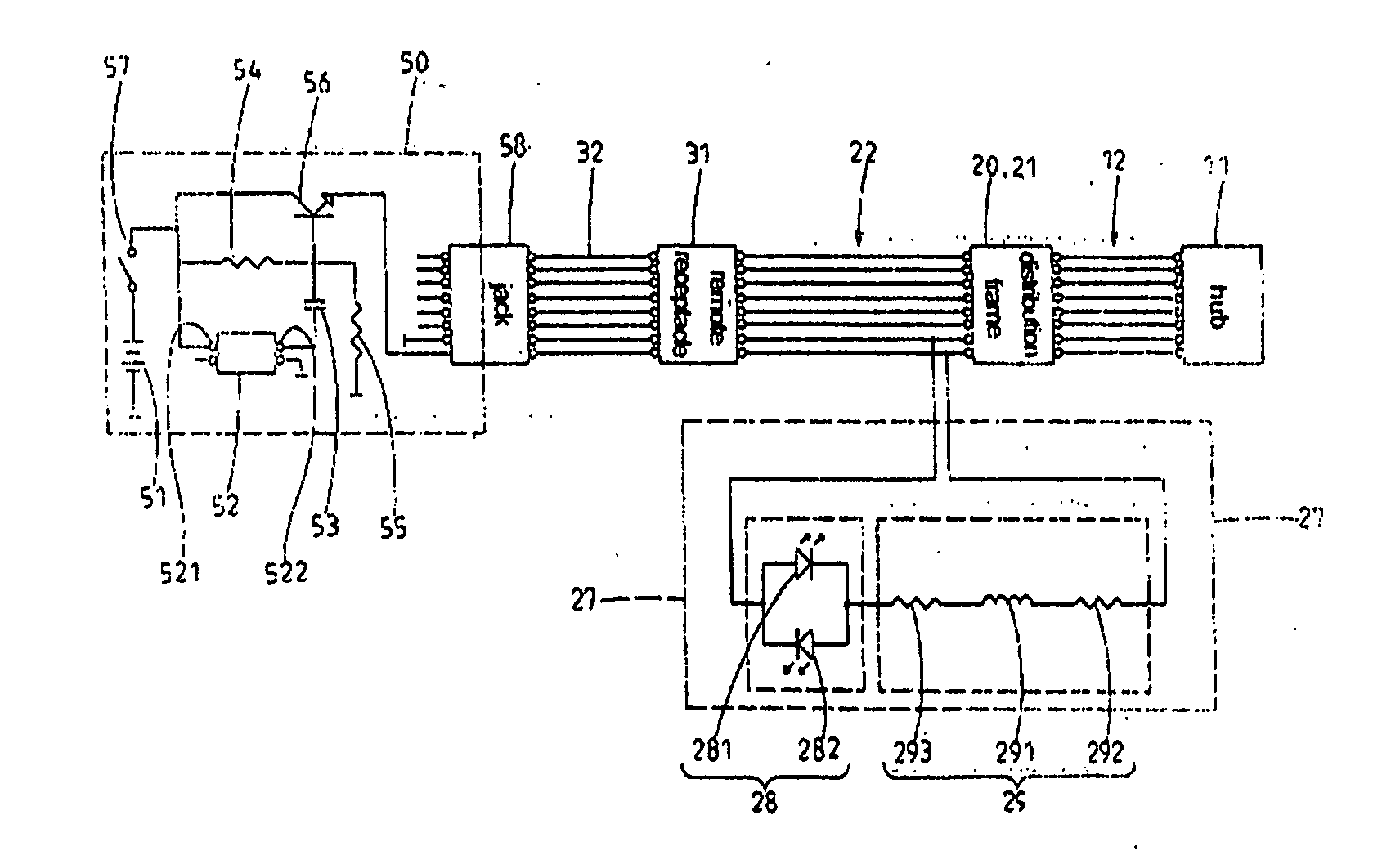
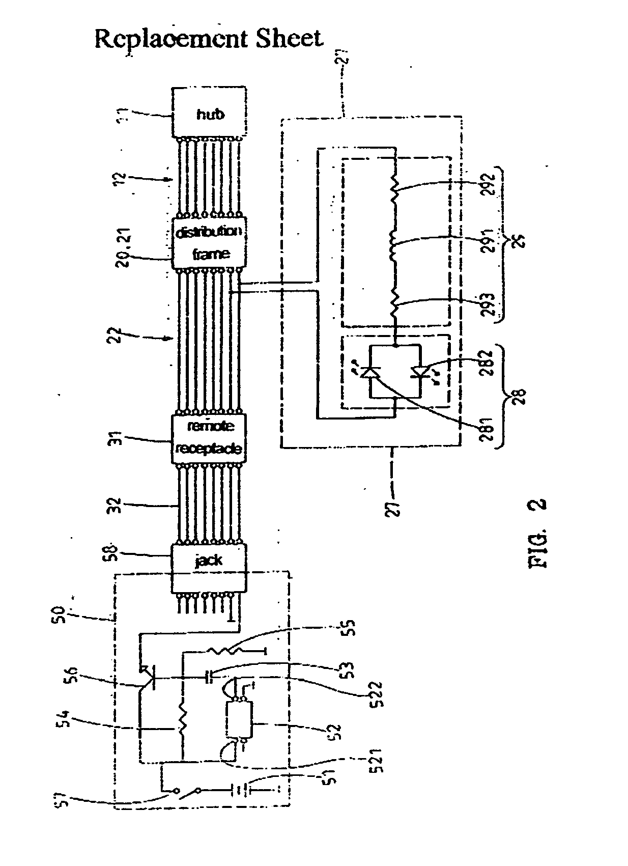
[0009] The light emitting means emit light when the testing device applies a testing voltage to the contacts. The testing voltage is a low-frequency voltage signal having a frequency higher than 200 Hz that creates a circuit impedance higher than an impedance of the filtering means when passing through the hub, thereby decaying and filtering the low-frequency voltage signal and allowing locating test while the server system is on-line.

Problems solved by technology

Management of the wires (or cables), e.g., identifying which jack on the patch panel is connected to which end user located at what remote location, is thus a critical issue in such a large server system.
Conventional methods for wire pair identification are labor-intensive and time-consuming.
The network jack in the working area could not be rapidly located to the associated network receptacle, leading to troublesome locating of the wire pairs.
However, when the wiring procedure is completed (i.e., connection to servers is completed), relocating the wire pairs of the wiring system would cause short circuit, as the voltage of the testing signals is a voltage of low direct current that will result in low impedance of the circuits for the electric components in the servers.
Hence, the light emitting means built in the group wiring system could not function.
As a result, relocating of the wire pairs of the wiring system requires removal of all of the server connection, which is labor-intensive and time-consuming.

Method used


Image

  • Group wiring system allowing locating of wire pairs and method for locating wire pairs in group wiring system
  • Group wiring system allowing locating of wire pairs and method for locating wire pairs in group wiring system
  • Group wiring system allowing locating of wire pairs and method for locating wire pairs in group wiring system

Examples


Embodiment Construction

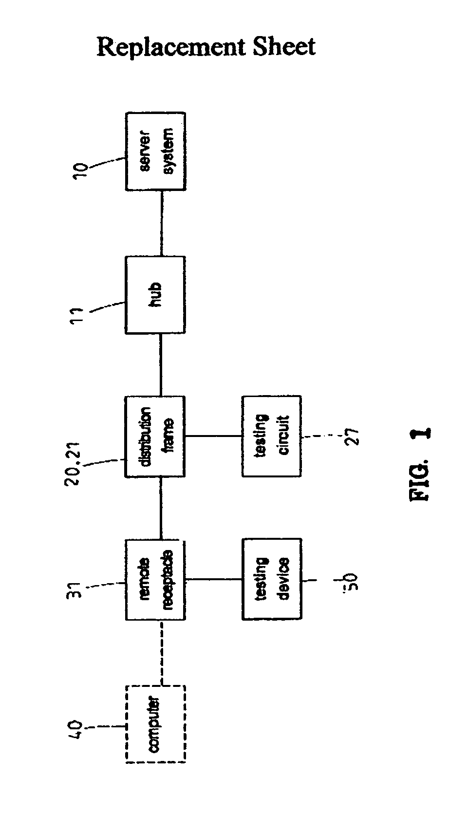
[0019] Referring to FIGS. 1 and 2, a group wiring system in accordance with the present invention comprises a hub 11, a distribution frame 20 electrically connected to the hub 11, a plurality of remote receptacles 31, and a testing device 50. The hub 11 may be a hub of a server system 10. The distribution frame 20 includes a plurality of wire pair receptacles 21 respectively in association with the remote receptacles 31. The hub 11 is connected to the distribution frame 20 via jump wires 12 for networks. Each wire pair receptacle 21 is connected via a conductive wire 22 (such as a network cable) to an associated one of the remote receptacles 31. Each remote receptacle 31 is normally connected to a computer 40 in a working area via jump wires 12 for networks. Further, each remote receptacle 31 is connected to the testing device 50 during testing of wire pair locations.

[0020] Referring to FIG. 3, the distribution frame 20 includes a panel 23 to which the wire pair receptacles 21 are ...


PUM


Abstract

A group wiring system includes a hub of a server system, a distribution frame including a plurality of wire pair receptacles, a plurality of remote receptacles, a testing device, and a plurality of testing circuits. Each testing circuit is coupled between conductive wires of contacts of an associated wire pair receptacle. Each testing circuit includes a light emitting device and a filtering device. The light emitting device emits light when the testing device applies a testing voltage to the contacts. The testing voltage is a low-frequency voltage signal having a frequency higher than 200 Hz that creates a circuit impedance higher than an impedance of the filtering device when passing through the hub, thereby decaying and filtering the voltage signal and allowing locating test while the server system is on-line. A method for locating wire pairs in a group wiring system is also disclosed.

Description

FIELD OF THE INVENTION [0001] The present invention relates to a group wiring system allowing locating of wire pairs. The present invention also relates to a method for locating wire pairs in a group wiring system. BACKGROUND OF THE INVENTION [0002] A typical communication system usually involves hundreds or even thousands of end users located at different sites or places sharing the service provided by the same server system. Some end users may connect to the server system from the internet through modems. Some end users may connect to the server system via local servers which may be far away from the server system. Some end users may connect to the server system by using hubs which may be located in the same building but different floors of the server system. Some end users may connect to the server system through a jack or socket near their working tables. Some end users may use wireless networking devices and wireless hubs to access the server system. Thousands of wires coming f...

Claims


Application Information

Patent Timeline
IPC IPC(8): G01R31/08
CPCG01R31/023G01R31/60
Inventor KU, YING-MINGLEE, YI-HUANGTSENG, TIEN-CHI
Owner WUXI UNIVERSAL NETWORK CORP
Learn More