Exposure apparatus, exposure method, and method for producing device

Active Publication Date: 2007-10-18
NIKON CORP
View PDF7 Cites 23 Cited by
  • Summary
  • Abstract
  • Description
  • Claims
  • Application Information

AI Technical Summary

Benefits of technology

[0016] According to the exposure apparatus of the third aspect of the present invention, the exposure method of the first aspect of the present invention can be used. Further, when the exposure apparat

Problems solved by technology

However, when the two patterns are simultaneously within the illumination area, it is difficult to set illumination conditions individually for the patterns respectively.
Therefore, it is difficult to optimize the illumination condition for each of the first and second patterns on each of the entire surface of the first and second patterns.
In addition, when the illumination condi

Method used


Image

  • Exposure apparatus, exposure method, and method for producing device
  • Exposure apparatus, exposure method, and method for producing device
  • Exposure apparatus, exposure method, and method for producing device

Examples


Example

[0027] In the following, an example of a preferred embodiment of the present invention will be described with reference to the drawings. In this example, the present invention is applied to perform the double exposure by using a scanning exposure type exposure apparatus of the step-and-scan system.

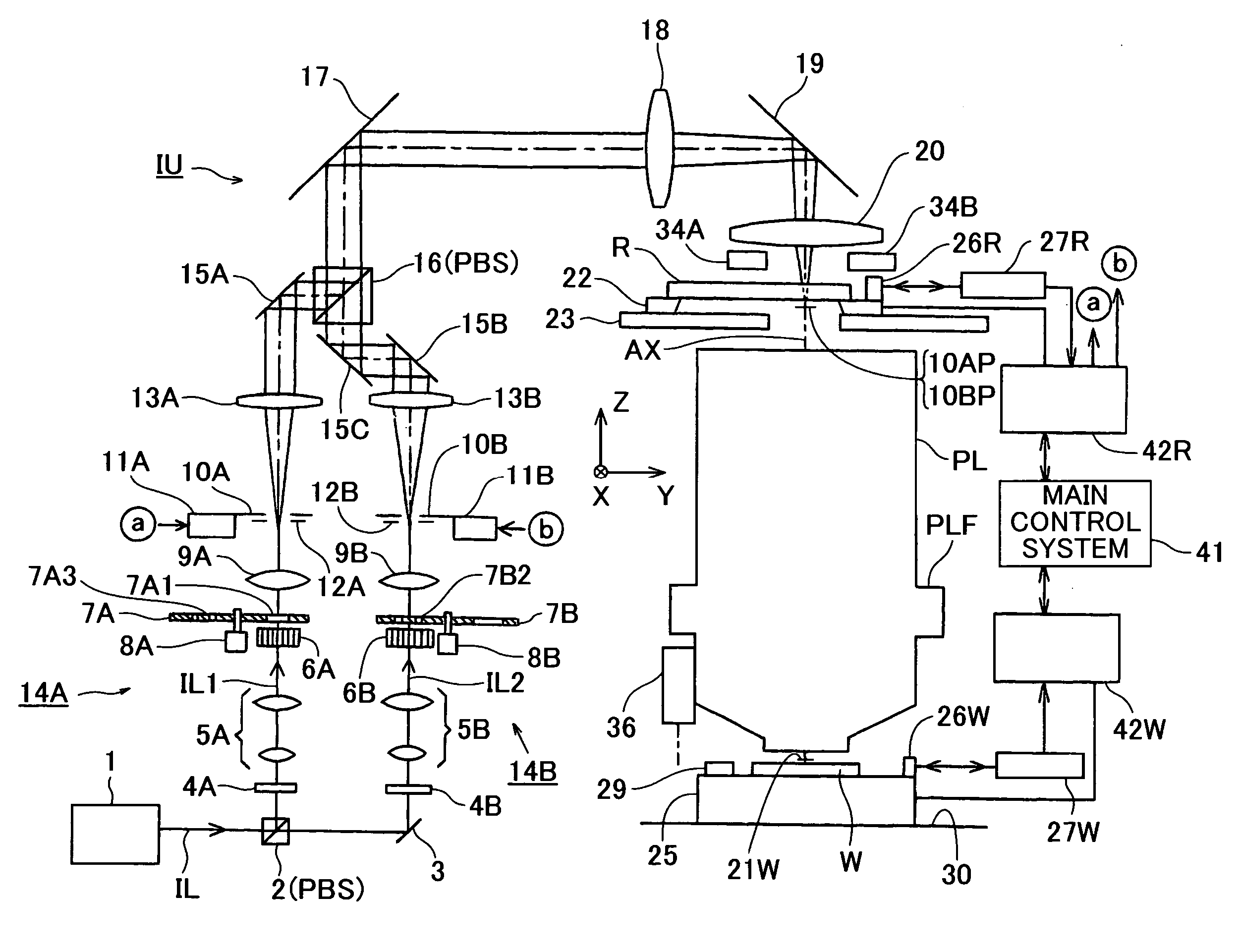
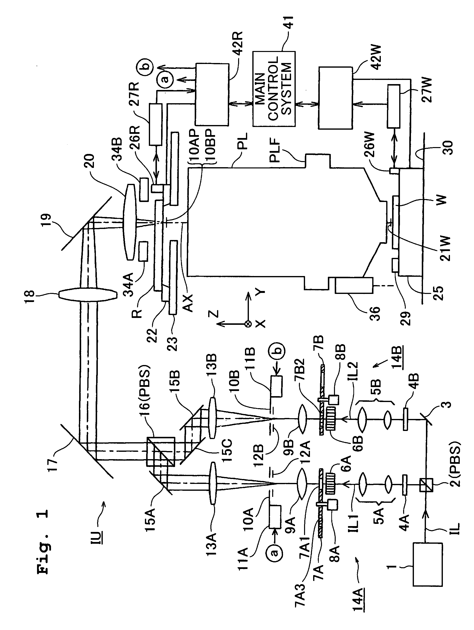
[0028]FIG. 1 shows an exposure apparatus of this example. In FIG. 1, the exposure apparatus includes an exposure light source 1; an illumination optical system IU which illuminates a reticle R as the mask with an exposure light (exposure light beam) from the exposure light source 1; a reticle stage 22 which moves while holding the reticle R; a projection optical system PL which projects an image of a pattern in an illumination area on the reticle R onto a wafer W as the substrate on which a resist (photosensitive material) is coated; a wafer stage 25 which moves while holding the wafer W; a drive mechanism for these stages; and a main control system 41 constructed of a computer which inte...


PUM


Abstract

The present invention provides an exposure method which illuminates each of patterns, to be subjected to double exposure, on entire surfaces thereof in optimal illumination conditions respectively, and which performs the exposure with high throughput. Upon transferring a pattern of a reticle onto a wafer by the scanning exposure method, first and second pattern areas are formed in advance on the reticle to be adjacent in the scanning direction, and when the first and second pattern areas simultaneously pass across a field of a projection optical system, the first pattern area is illuminated in a first illumination condition by using a first illumination slit of which width in the scanning direction is gradually narrowed, and the second pattern area is illuminated in a second illumination condition by using a second illumination slit of which width in the scanning direction is gradually widened, to thereby expose the wafer.

Description

REFERENCE TO RELATED APPLICATION [0001] The present application claims priority from Japanese Patent Application No. 2006-058739 filed on Mar. 3, 2006 and U.S. Provisional Patent Application No. 60 / 851,044 filed on Oct. 12, 2006, the disclosures of which are incorporated herein by reference in their entirety.BACKGROUND OF THE INVENTION [0002] 1. Field of the Invention [0003] The present invention relates to an exposure technique for transferring a pattern onto a substrate such as a wafer in the lithography process for producing various devices such as a semiconductor device, a liquid crystal display device, or a thin-film magnetic head, and in particular, the present invention is preferably used for multiple exposure, for example, double exposure of a substrate. [0004] 2. Description of the Related Art [0005] The double exposure method is one of the exposure methods used for transferring a pattern of a reticle as a mask onto a wafer (or glass plate or the like) coated with a resist ...

Claims


Application Information

Patent Timeline
IPC IPC(8): G03B27/52
CPCG03F7/70466G03B27/52
Inventor SHIBAZAKI, YUICHIKOMATSUDA, HIDEKI
Owner NIKON CORP
Why Eureka
Try Eureka