Illuminating device, electro-optical device, and electronic apparatus

a technology of electrooptical devices and illumination devices, applied in the direction of optical radiation measurement, instruments, semiconductor lasers, etc., can solve the problems of increasing manufacturing costs, insufficient illumination light control, and insufficient detection values of photodetectors, and achieve the effect of accurately detecting illumination light and high accuracy

Active Publication Date: 2007-10-18
JAPAN DISPLAY WEST
View PDF2 Cites 14 Cited by
  • Summary
  • Abstract
  • Description
  • Claims
  • Application Information

AI Technical Summary

Benefits of technology

[0009]An advantage of some aspects of the invention is that it provides an illuminating device which is capable of controlling illumination light with high accuracy by accurately detecting the illu

Problems solved by technology

Therefore, there is a case in which detection values of the photodetectors may not sufficiently reflect the entirety of the illumination light emitted from the light-emitting surface of the light guide plate.
Even when the light sources are controlled on the basis of t

Method used


Image

  • Illuminating device, electro-optical device, and electronic apparatus
  • Illuminating device, electro-optical device, and electronic apparatus
  • Illuminating device, electro-optical device, and electronic apparatus

Examples


first embodiment

Illuminating Device

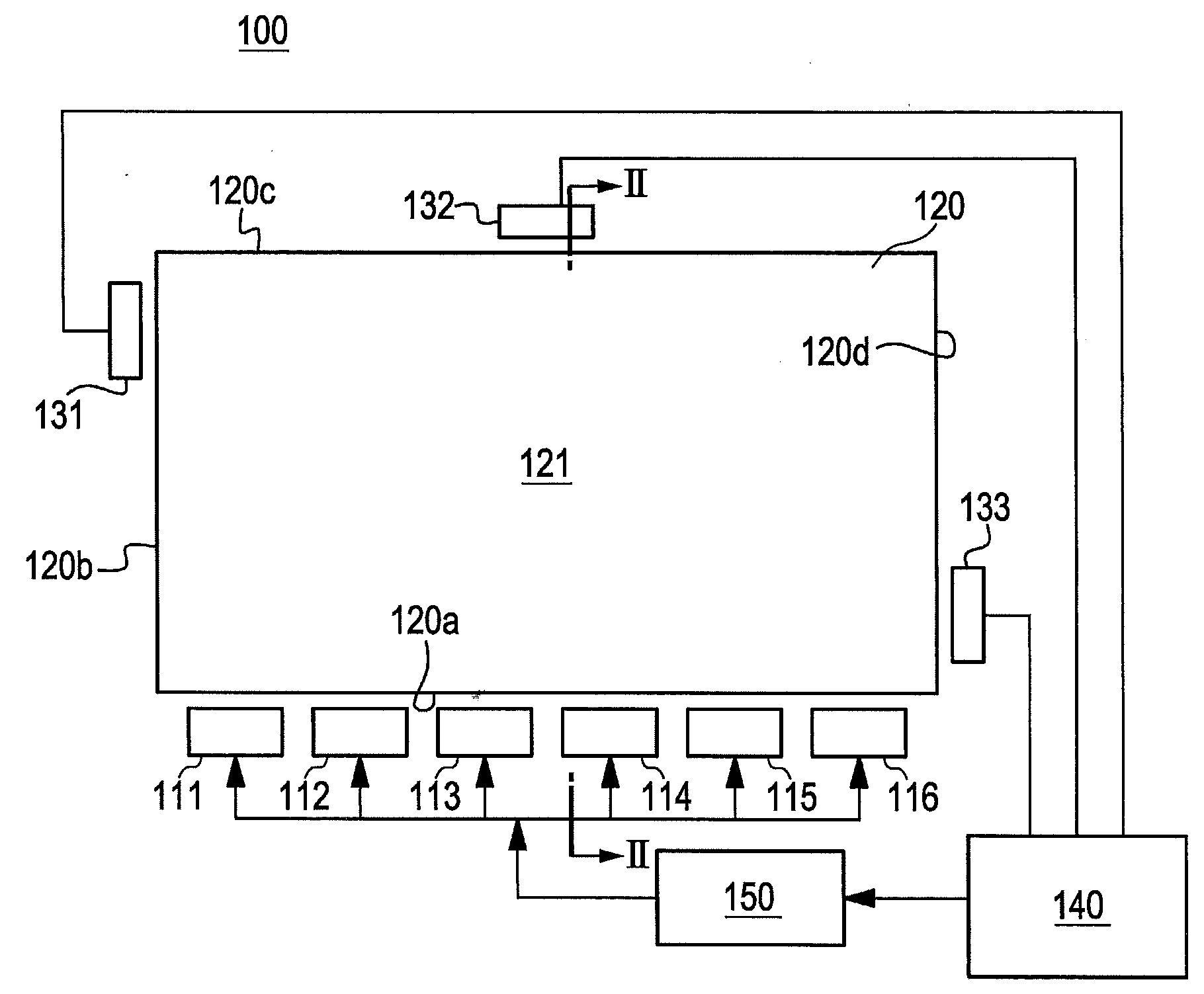
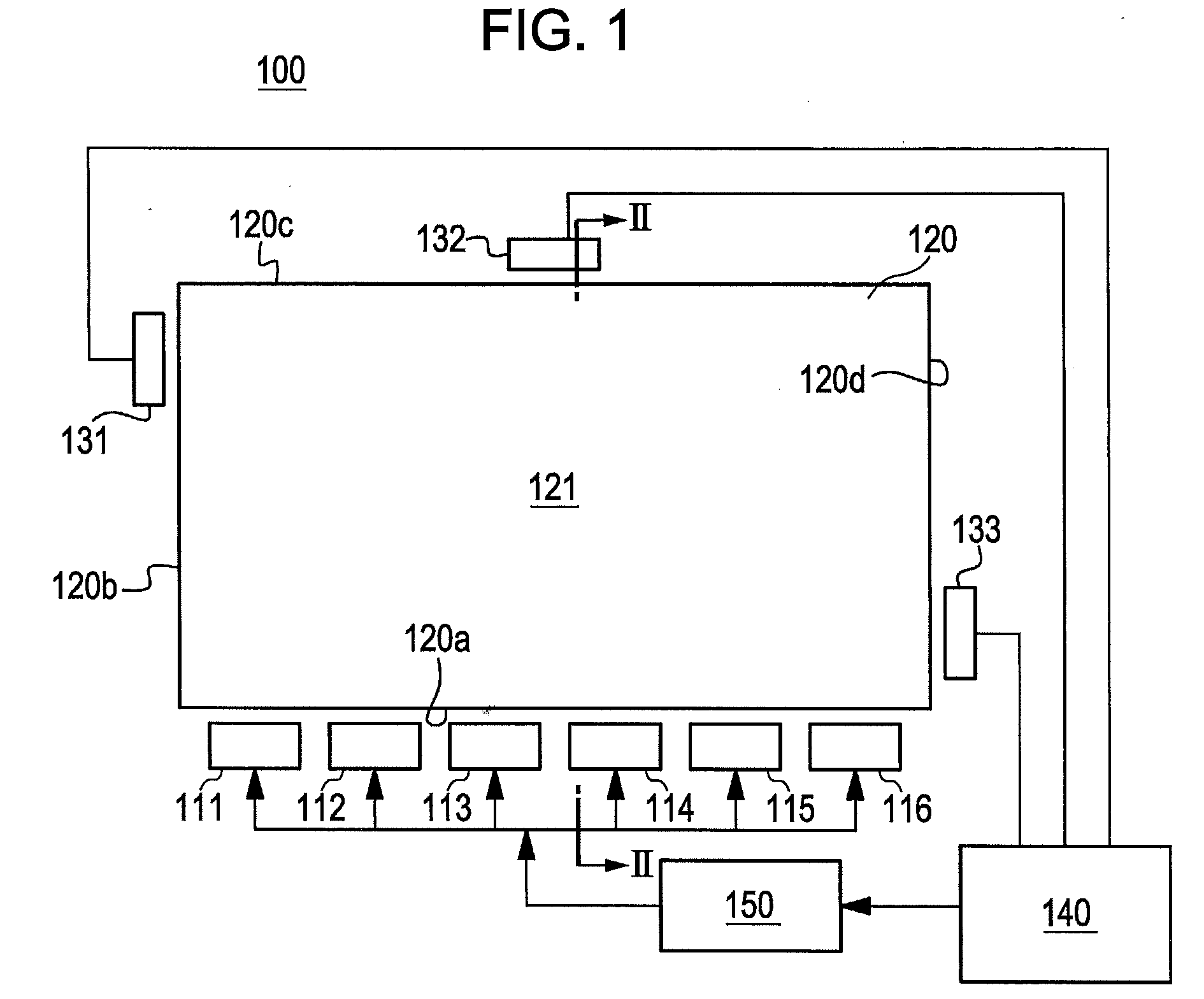
[0037]FIG. 1 is a schematic view illustrating the structure of an illuminating device according to a first embodiment of the invention. An illuminating device 100 includes a plurality of light sources (in the example of FIG. 1, six light sources) 111, 112, 113, 114, 115, and 116, a light guide plate 120 that receives light emitted from the light sources from a light incident surface 120a, which is one of the end faces thereof, and emits the light from a light-emitting surface 121 that is one of the plate surfaces thereof, a plurality of photodetectors (in the example of FIG. 1, three photodetectors) 131, 132, and 133 that are disposed at different positions around the light guide plate 120, a detecting circuit 140 that calculates a representative value on the basis of detection values that are obtained individually by the photodetectors 131, 132, and 133, and a control circuit 150 that controls the light sources 111 to 116 on the basis of a result obtained by comp...

second embodiment

[0067]Next, an illuminating device 200 according to a second embodiment will be described in detail with reference to FIG. 6. FIG. 6 is a schematic plan view illustrating a planar arrangement of light sources, a light guide plate, and photodetectors of the illuminating device 200 according to a second embodiment. In this embodiment, the same constituent elements as those of the illuminating device 100 according to the first embodiment are denoted by the same reference numerals. Thus, the description thereof will be omitted.

[0068]This embodiment includes a plurality of photodetectors 231, 232, and 233 having the same structures as the photodetectors 131, 132, and 133 of the illuminating device 100 according to the first embodiment. However, the photodetectors 231 and 232 are disposed to face both end portions of left and right of an end face 120c of the light guide plate 120. Further, the photodetector 233 is disposed to face a bottom surface of the light guide plate 120. More specif...

third embodiment

[0072]Next, an illuminating device 300 according to a third embodiment will be described with reference to FIG. 7. FIG. 7 is a schematic plan view illustrating a planar arrangement of light sources, a light guide plate, and photodetectors of the illuminating device according to the third embodiment. Further, the same constituent elements as those of the illuminating device 100 according to the first embodiment are denoted by the same reference numerals. Thus, the description thereof will be omitted.

[0073]In this embodiment, a photodetector 331 is disposed to face one end portion of an end face 120c, and a photodetector 332 is disposed to face a central portion of the end face 120c. Further, a photodetector 333 is disposed to face an end face 120d that is adjacent to an end portion opposite to the one end portion of the end face 120c which the photodetector 331 faces.

[0074]In this embodiment, by the photodetectors 331 and 332 that face the end portion and the central portion, respect...


PUM


Abstract

An illuminating device includes a plurality of light sources, a light guide plate that has plate surfaces on front and rear sides and a plurality of end faces formed around the plate surfaces, receives light emitted from the plurality of light sources through a light incident surface, which is at least one end face among the plurality of end faces, and emits the light through a light-emitting surface, which is one of the plate surfaces, a plurality of photodetectors that are disposed to face the end faces or the plate surfaces of the light guide plate, and a light source control unit that controls light emission of the plurality of light sources on the basis of the output of the plurality of photodetectors. The plurality of photodetectors include at least two photodetectors including light receiving surfaces that face the end faces or the plate surfaces in different directions from each other.

Description

[0001]The entire disclosure of Japanese Patent Application No. 2006-110916, filed Apr. 13, 2006 is expressly incorporated by reference herein.BACKGROUND[0002]1. Technical Field[0003]The present invention relates to an illuminating device, to an electro-optical device, and to an electronic apparatus. In particular, the invention relates to a structure of an illuminating device having a function of controlling light emission of light sources according to detection values of photodetectors.[0004]2. Related Art[0005]In a known illuminating device, light emitted from light sources, such as LEDs, is made incident on a light guide plate, propagates through the light guide plate, and is emitted from a light-emitting surface of the light guide plate. Such an illuminating device has been used as, for example, a planar illuminating device, such as a backlight, for illuminating a liquid crystal panel.[0006]In the illuminating device, uniformity of luminance of light emitted from a light-emittin...

Claims


Application Information

Patent Timeline
IPC IPC(8): H01S5/00H01K1/30
CPCG02B6/0068G02B6/4202G09G2360/145G09G2320/0666G09G3/3413
Inventor KAWAKAMI, HISANORI
Owner JAPAN DISPLAY WEST
Why Eureka
Try Eureka