Gas turbine engine component suction side trailing edge cooling scheme

a gas turbine engine and cooling scheme technology, applied in the direction of machines/engines, liquid fuel engines, mechanical equipment, etc., can solve the problems of degrading cooling air provided by film cooling air along the trailing edge, and affecting the cooling effect of gas turbine engines. , to achieve the effect of increasing the convective surface area, increasing the height, and increasing the cooling

Inactive Publication Date: 2007-10-18
RAYTHEON TECH CORP
View PDF4 Cites 19 Cited by
  • Summary
  • Abstract
  • Description
  • Claims
  • Application Information

AI Technical Summary

Benefits of technology

[0011] To improve cooling in the area mentioned above, supplemental pedestals extend from an inner wall at the suction side and toward the impingement tube. In a disclosed embodiment, there are no impingement holes formed in the impingement tube over the length of the impingement tube that has the supplemental pedestals. Impingement holes are formed in the tube at the pressure side along the same length.
[0013] In other features, the supplemental pedestals increase in height in a direction from the leading edge toward the trailing edge. Further, the impingement tube is spaced from the inner wall of the suction side by a greater distance as the impingement tube extends from a leading edge end toward a trailing edge end. In this manner, more air flow is directed along the suction side and over the supplemental pedestals, providing greater cooling.
[0014] One main function of having the pedestals increase in height is to increase convective surface area and increase fin efficiency. This same effect could be achieved with trip strips or dimples. In fact, the term “pedestals” as utilized in this application and in the claims, extends to more than the cylindrical-shaped elements that are illustrated in the drawings of this application. The term “pedestals” would extend to any structure extending outwardly of the wall and into the flow path. The longer pedestals also serve to push the downstream end of the impingement tube toward the pressure side wall. This limits the area in which flow can enter the trailing edge via the pressure side, providing a seal between the two regions. Another function is to allow the suction side flow to diffuse into the trailing edge pedestal bank. This effect “guides” the air into the wider trailing edge cavity and increases static pressure in the transition region. This static pressure increase also helps to seal off the pressure side flow from entering the trailing edge.

Problems solved by technology

Numerous components within the gas turbine engine are subject to high levels of heat during operation.
For various reasons, the location and amount of film cooling may be limited.
However, the cooling provided by this film cooling air degrades along a direction toward the trailing edge.
Thus, and in an area roughly adjacent with an end of the impingement tube area, there is a portion of the suction wall that may not receive adequate cooling.
In addition to this degradation, the impingement in this region also becomes somewhat ineffective due to “cross-flow degradation.” This is the result of the accumulation of coolant that has been injected from earlier regions.
As more flow enters the cavity between the tube and the wall and heads toward the trailing edge, the impingement jets begin to become less effective.

Method used


Image

  • Gas turbine engine component suction side trailing edge cooling scheme
  • Gas turbine engine component suction side trailing edge cooling scheme
  • Gas turbine engine component suction side trailing edge cooling scheme

Examples


Embodiment Construction

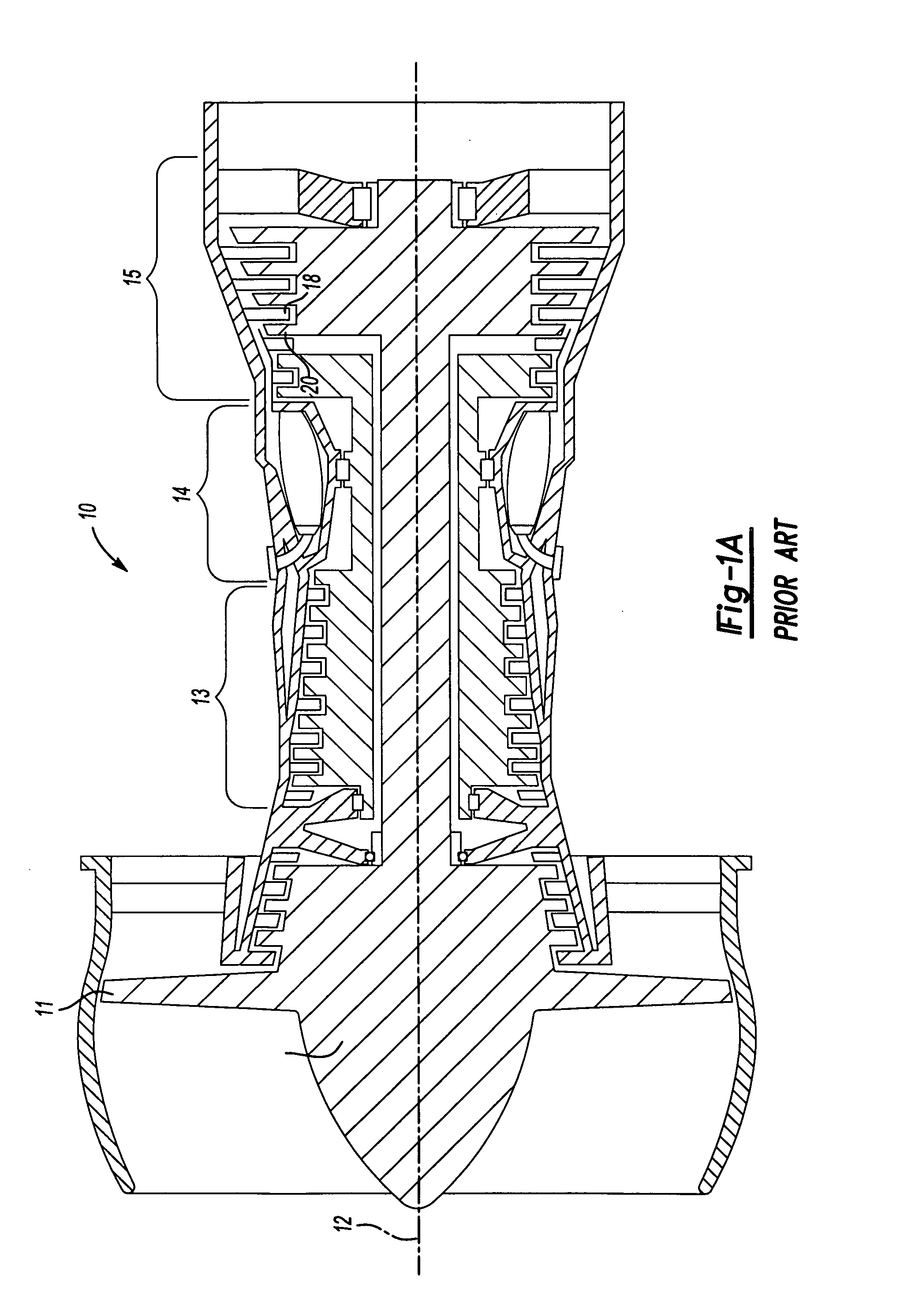
[0022]FIG. 1A shows a gas turbine engine 10. As known, a fan section 11 moves air and rotates about an axial center line 12. A compressor section 13, a combustion section 14, and a turbine section 15 are also centered on the axial center line 12. FIG. 1A is a highly schematic view, however, it does show the main components of the gas turbine engine. Further, while a particular type of gas turbine engine is illustrated in this figure, it should be understood that the present invention extends to other types of gas turbine engines.

[0023] The turbine section 15 includes a rotor having turbine blades 20, and stationary vanes 18. As mentioned above, these turbine blades 20 and vanes 18 become quite hot as the products of combustion pass over them to create power. The present invention is directed to cooling schemes for better cooling such components.

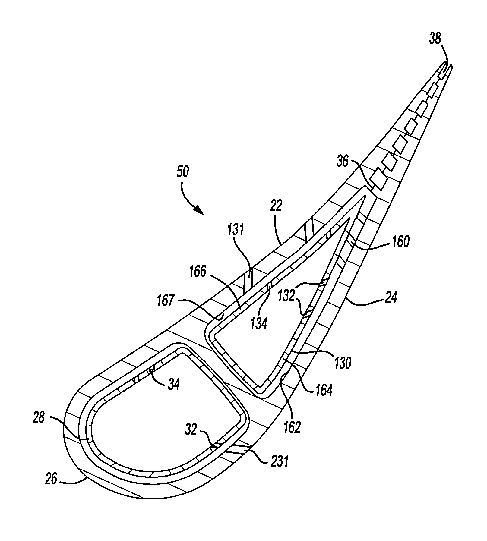
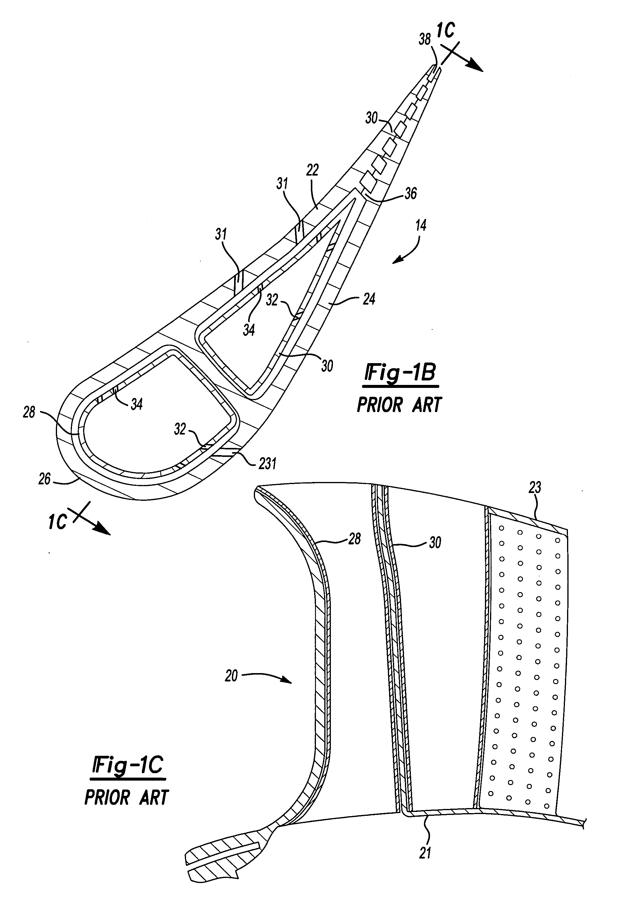
[0024] A gas turbine engine component is illustrated in FIG. 1B, as a stationary vane. However, it should be understood that the present i...


PUM


Abstract

A gas turbine engine component has a cooling scheme that utilizes an impingement tube to cool the suction wall and the pressure wall of a mid portion of an airfoil. The impingement tube is formed to not have impingement holes on an end of the impingement tube spaced toward the trailing edge along the suction wall. Impingement holes are formed in the same portion on a side of the impingement tube facing the pressure wall. Pedestals extend from an inner face of the suction wall toward the impingement tube in this area. The use of the pedestals over this area provides greater cooling to a focused area on the suction wall of the airfoil that might otherwise receive inadequate film cooling.

Description

[0001] This invention was made with government support under Contract No. N-00019-02-C-3003 awarded by the United States Navy. The government therefore has certain rights in this invention.BACKGROUND OF THE INVENTION [0002] This application relates to a cooling scheme for a gas turbine engine component, such as a stationary vane, wherein an impingement tube is located within a cooling air channel, and pedestals are aligned with a portion of the tube. [0003] Gas turbine engines are provided with a number of functional sections, including a fan section, a compressor section, a combustion section, and a turbine section. Air and fuel are combusted in the combustion section. The products of the combustion move downstream, and pass over a series of turbine rotors, driving the rotors to create power. [0004] Numerous components within the gas turbine engine are subject to high levels of heat during operation. As an example, a turbine section will have a plurality of vanes over which high te...

Claims


Application Information

Patent Timeline
Patent Type & Authority Applications(United States)
IPC IPC(8): F01D5/18
CPCF01D5/189F05D2260/22141F05D2260/2212F05D2260/201
Inventor DEVORE, MATTHEWPAAUWE, CORNEIL
Owner RAYTHEON TECH CORP
Why Eureka
Try Eureka