Dynamically configuring and verifying routing information of broadcast networks using link state protocols in a computer network

a technology of link state protocol and computer network, applied in the field of dynamically configuring and verifying routing information of broadcast network using link state protocol in the computer network, can solve the problems of link state protocol use, burdensome management of interconnected computer network,

Active Publication Date: 2007-10-18
CISCO TECH INC
View PDF31 Cites 348 Cited by
  • Summary
  • Abstract
  • Description
  • Claims
  • Application Information

AI Technical Summary

Benefits of technology

[0020] Advantageously, the novel technique dynamically configures and verifies routing information of broadcast networks using link state protocols in a computer network. By confirming that a next-hop to a destination address prefix is directly addressable, the novel technique efficiently and dynamically ensures that correct routing information is used in broadcast networks where the next-hop is conventionally assumed to be reachable, thus alleviating the need for cumbersome manual configuration or other network configurations. In particular, the present invention prevents the installation of unreachable next-hop routes at routers within the broadcast network (e.g., spoke routers or routers within a partial mesh network). Also, failed / removed routes or routes with otherwise limited connectivity between the router and the next-hop may be avoided by periodically confirming the reachability and replacing the failed / removed next-hop routes with routes to the designated router.

Problems solved by technology

Since management of interconnected computer networks can prove burdensome, smaller groups of computer networks may be maintained as routing domains or autonomous systems.
One problem associated with broadcast networks is that the link state protocols used in the networks assume that the routers are fully meshed.
As those skilled in the art will understand, however, this is not always the case.
If, as in the above circumstances, the router is unable to reach the next-hop directly, the router will be unable to forward traffic to the destination address prefix due to the incorrect next-hop information, and traffic may be lost.
This solution may be difficult to implement and does not adjust to changes in the network.
For example, if an advertised next-hop is reachable sometimes and not reachable at other times, (e.g., due to mobility of routers, link flapping, etc.), the static route is inefficient at providing the best path to the destination.
This option is generally a clumsy configuration, creating larger LSDBs in the routers of the network and is difficult to scale in large networks, as will be understood by those skilled in the art.
Again, by operating under the assumption that the network is a broadcast network, link state protocols may cause routing errors, directing a router to reach a particular destination address prefix through a next-hop that is, in fact, unreachable to the router.

Method used


Image

  • Dynamically configuring and verifying routing information of broadcast networks using link state protocols in a computer network
  • Dynamically configuring and verifying routing information of broadcast networks using link state protocols in a computer network
  • Dynamically configuring and verifying routing information of broadcast networks using link state protocols in a computer network

Examples


Embodiment Construction

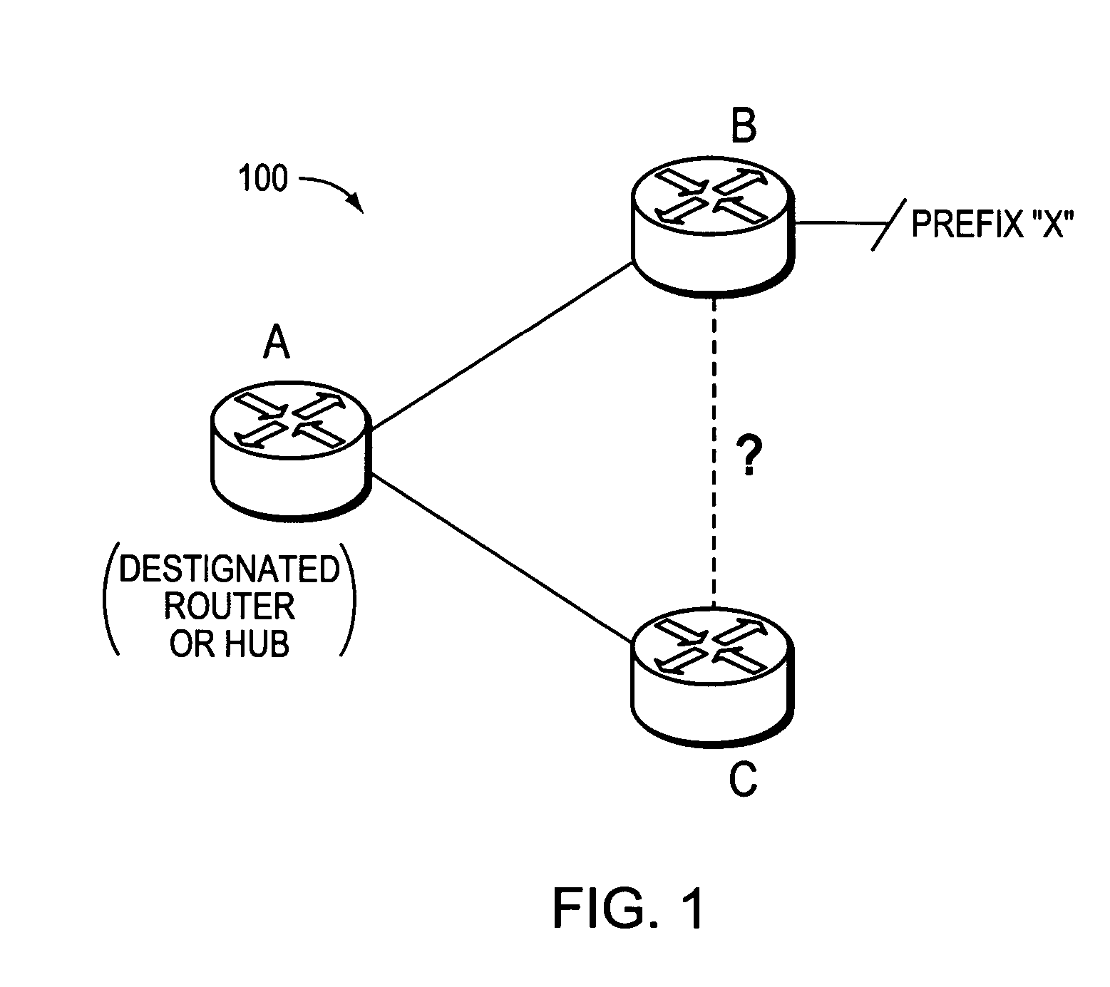
[0029]FIG. 1 is a schematic block diagram of an exemplary computer network 100 that may be advantageously used with the present invention. The network 100 comprises a plurality of interconnected network nodes, such as routers A, B, and C. Illustratively, the routers may be interconnected by one or more links, such as, e.g., over local area network (LAN) links, wireless LANs, etc., to form the network 100. Each router may be used to reach one or more destination address prefixes, such as prefix X from router B as shown. Notably, network 100 may be configured as a full mesh network, where each router is interconnected to each and every other router of the network, or may be configured as a partial mesh network, such as a hub-and-spoke network, as will be understood by those skilled in the art. Those skilled in the art will understand that any number of nodes, links, prefixes, etc., may be used in the computer network 100 and connected in a variety of ways, and that the view shown here...


PUM


Abstract

A technique dynamically configures and verifies routing information of broadcast networks using link state protocols in a computer network. According to the novel technique, a router within the broadcast network receives a link state protocol routing information advertisement from an advertising router, e.g., a designated router or other adjacent neighbor. The router learns of a next-hop router (“next-hop”) to reach a particular destination from the advertisement, and determines whether the next-hop is located within the same broadcast network (e.g., subnet) as the designated router. If so, the router further determines whether the next-hop is directly addressable (i.e., reachable), such as, e.g., by checking for link adjacencies to the next-hop or by sending request / reply messages (e.g., echo messages or “ping” messages) to the next-hop. In the event the next-hop for the destination is not directly addressable by the router (e.g., no adjacency or reply), the router installs a route to the destination via the designated router. Otherwise, the router installs a route to the destination via the next-hop.

Description

BACKGROUND OF THE INVENTION [0001] 1. Field of the Invention [0002] The present invention relates to computer networks and more particularly to dynamically configuring and verifying routing information of broadcast networks using link state protocols in a computer network. [0003] 2. Background Information [0004] A computer network is a geographically distributed collection of nodes interconnected by communication links and segments for transporting data between end nodes, such as personal computers and workstations. Many types of networks are available, with the types ranging from local area networks (LANs) to wide area networks (WANs). LANs typically connect the nodes over dedicated private communications links located in the same general physical location, such as a building or campus. WANs, on the other hand, typically connect geographically dispersed nodes over long-distance communications links, such as common carrier telephone lines, optical lightpaths, synchronous optical net...

Claims


Application Information

Patent Timeline
Patent Type & Authority Applications(United States)
IPC IPC(8): G06F15/173H04L45/02H04L45/16H04L45/74
CPCH04L45/02H04L45/16H04L12/66H04L12/28G06F15/173H04L45/54H04L45/03
Inventor RETANA, ALVARO E.LINDEM, ALFRED C. IIIWHITE, RUSS
Owner CISCO TECH INC
Why Eureka
Try Eureka