Electronic Compressed-Air System

a compressed air and electronic technology, applied in the direction of braking systems, braking components, transportation and packaging, etc., can solve problems such as complex known systems, and achieve the effect of largely eliminating compressed air reservoirs

Inactive Publication Date: 2007-10-25
WABCO EURO BVBA SPRL
View PDF5 Cites 21 Cited by
  • Summary
  • Abstract
  • Description
  • Claims
  • Application Information

AI Technical Summary

Benefits of technology

[0003] Generally speaking, in accordance with the present invention an improved compressed-air system is cons

Problems solved by technology

The known system is complex, since each load circui

Method used


Image

  • Electronic Compressed-Air System
  • Electronic Compressed-Air System

Examples


Embodiment Construction

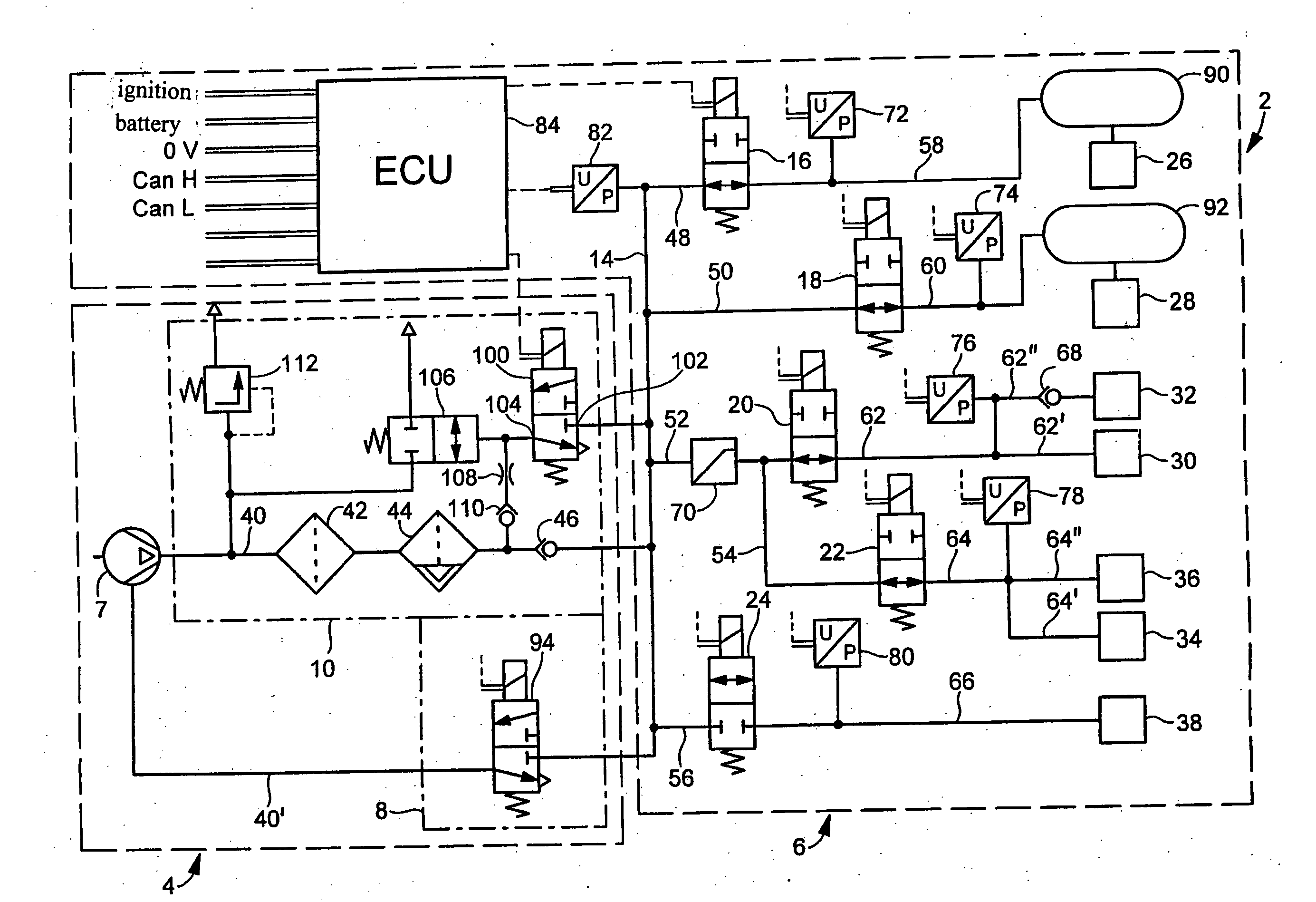
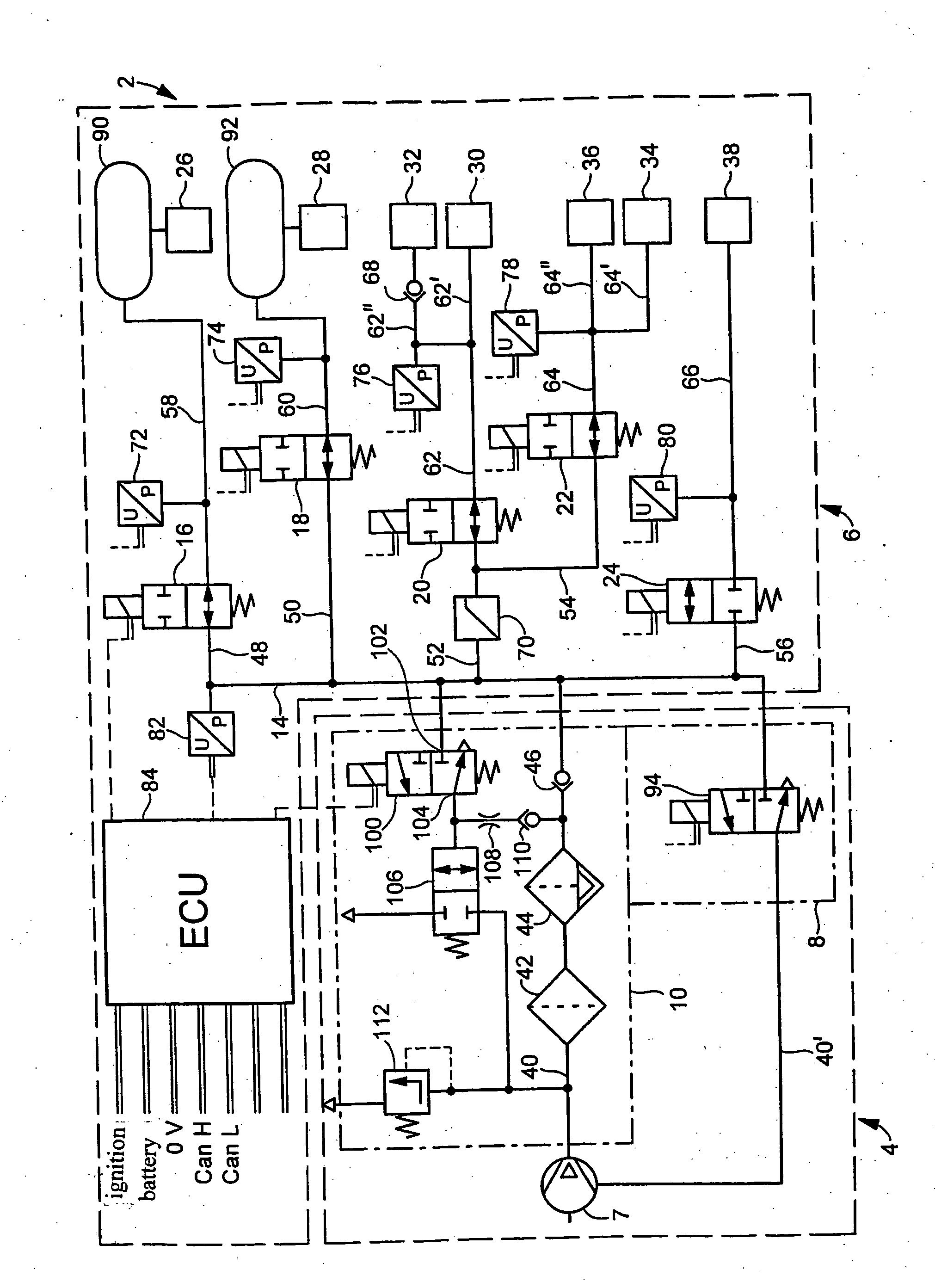
[0009] Referring now to FIG. 1, where pressurized-fluid lines are represented by solid lines and electrical lines by broken lines, there is shown a compressed-air system 2 with a compressed-air supply part 4 and a consumer part 6. Compressed-air supply part 4 comprises a compressor 7, a compressor control device 8 and an air-dryer part 10.

[0010] Consumer part 6 is provided with a compressed-air distributor line 14, a plurality of electrically actuatable valves, preferably solenoid valves 16, 18, 20, 22, 24 with restoring springs and a plurality of load circuits 26, 28, 30, 32, 34, 36, 38 supplied with compressed-air via the solenoid valves.

[0011] From compressor 7, a compressed-air supply line 40 leads via a filter 42, an air dryer 44 and a check valve 46 to distributor line 14, from which there are branched off lines 48, 50, 52, 54, 56 leading to the solenoid valves. From the solenoid valves, compressed-air lines 58, 60, 62, 64, 66 lead to the load circuits. Line 62 splits into l...


PUM


Abstract

An electronic compressed-air system includes a compressed-air supply part having a compressor and a consumer part having load circuits. The load circuits are supplied with compressed-air via solenoid valves. At least one load circuit is provided with a pressure reservoir. The pressure in the load circuits is monitored by pressure sensors, whose signals are evaluated by an ECU that controls the solenoid valves. The load circuits include service-brake circuits having a compressed-air reservoir, secondary load circuits and a high-pressure circuit, wherein the solenoid valves of the service-brake circuits and the solenoid valves of the secondary load circuits are open in a de-energized normal state and the solenoid valve of the high-pressure circuit is closed in the de-energized normal state.

Description

BACKGROUND OF THE INVENTION [0001] The present invention relates to an electronic compressed-air system for vehicles. [0002] WO 98 / 47751 A1 describes a pneumatic vehicle brake system provided with a compressor, at least one air-load circuit, such as service-brake circuits, a parking-brake circuit, a low-pressure auxiliary circuit and a high-pressure circuit, wherein the circuits are provided with compressed-air reservoirs and demand valves. Between the compressor and the at least one load circuit, there are disposed first electrically actuatable valves, which are closed in the de-energized normal state, and, between the compressor and the auxiliary circuit, there is disposed a second electrically actuatable valve, which is open in the de-energized normal state. The valves are actuated by an electronic control unit. The outlet ports of the first valves of the air-load circuits are in communication via check valves with the outlet port of the second valve, which is open in the de-ener...

Claims


Application Information

Patent Timeline
IPC IPC(8): B60T13/68B60T13/26B60T17/02
CPCB60T13/26B60T17/004B60T17/02
Inventor DIEKMEYER, HEINRICHBORNHOF, HANS-ULRICHLIPPELT, FRANK-DIETMAR
Owner WABCO EURO BVBA SPRL
Why Eureka
Try Eureka