Motor blower unit

a motor and motor technology, applied in the field of patient ventilation systems, can solve the problems of not being able to achieve the required compressive flow at a high efficiency level, the configuration of the radial fan wheel as used in the muller reference is not understood to possess the ability to reduce noise, and the miniature fan as used in the muller reference is not understood to operate at a reduced noise level. , to achieve the effect of enhancing the compressive efficiency of the impeller, minimizing vane-

Active Publication Date: 2007-10-25
VYAIRE MEDICAL 211 INC
View PDF17 Cites 106 Cited by
  • Summary
  • Abstract
  • Description
  • Claims
  • Application Information

AI Technical Summary

Benefits of technology

[0017] Each one of the vanes has a vane height which is optimized such that during rotation of the impeller, aerodynamic losses are minimized. Such aerodynamic losses may occur due to the formation of fluid eddies as air inducted into the blower assembly is compressed by the impeller. In one embodiment of the blower assembly, the vane height is optimized such that the blower assembly produces a flow rate of up to approximately 125 liters per minute at a pressure of approximately 20 cm H2O using less than approximately 15 watts of input power at the motor assembly.
[0018] Furthermore, the blower assembly is configured such that the impeller rotates within relatively close proximity to the housing interior surface in order to further enhance the compressive efficiency of the impeller. In this regard, each one of the vanes defines an air gap between the free edge of the vane and the housing interior surface. The blower assembly and, more particularly, the bearing assembly is configured such that the air gap is maintained at less than approximately 0.0006 inches during rotation of the impeller and preferably, is maintained at approximately 0.0002 inches. The maintenance of the relatively small air gap minimizes vane-to-vane leakage as air is compressed by the blower assembly.
[0019] The impeller may include a downwardly t...

Problems solved by technology

Although the miniature fan of the Muller reference is disclosed as having a relatively small size of about 23 mm in height and 73 mm in width, the miniature fan is not believed to be suitable for certain applications such as in a CPAP device which requires an even smaller size and lower-weight blower assembly.
Furthermore, the configuration of the radial fan wheel as used in the Muller reference is not understood to possess the ability to produce the required compressive flow at a high efficiency level.
Furthermore, the miniature fan as used in the Muller reference is not understood to operate at a reduced noise level and with redu...

Method used


Image

  • Motor blower unit
  • Motor blower unit
  • Motor blower unit

Examples


Embodiment Construction

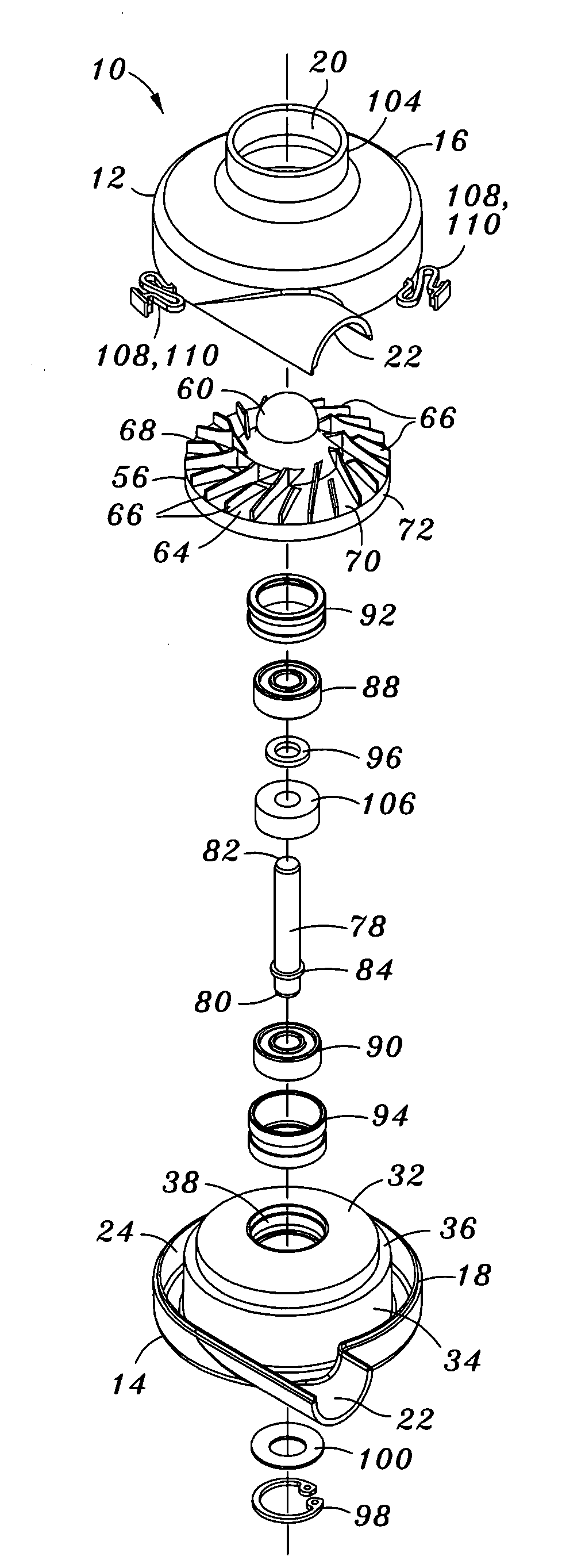
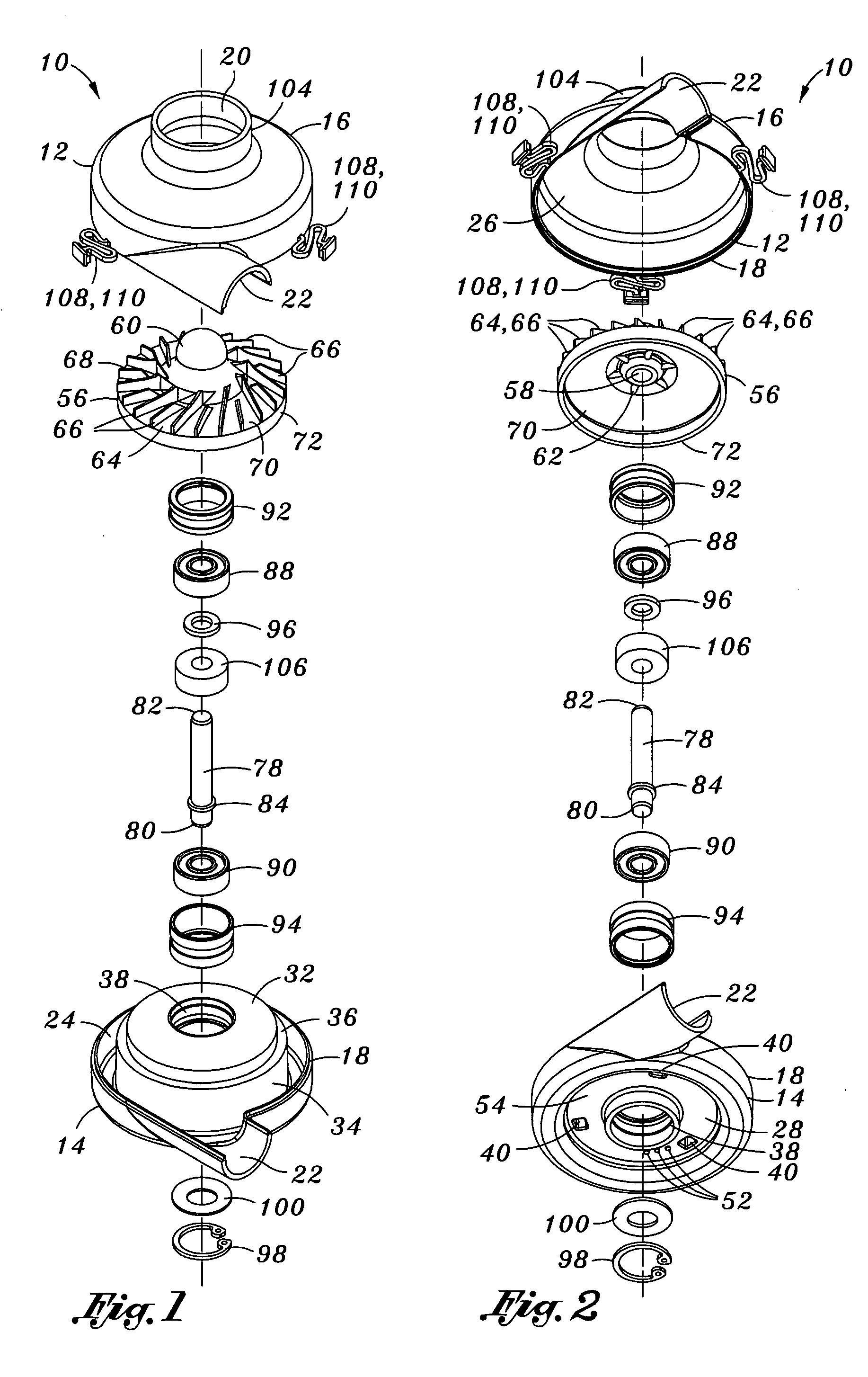
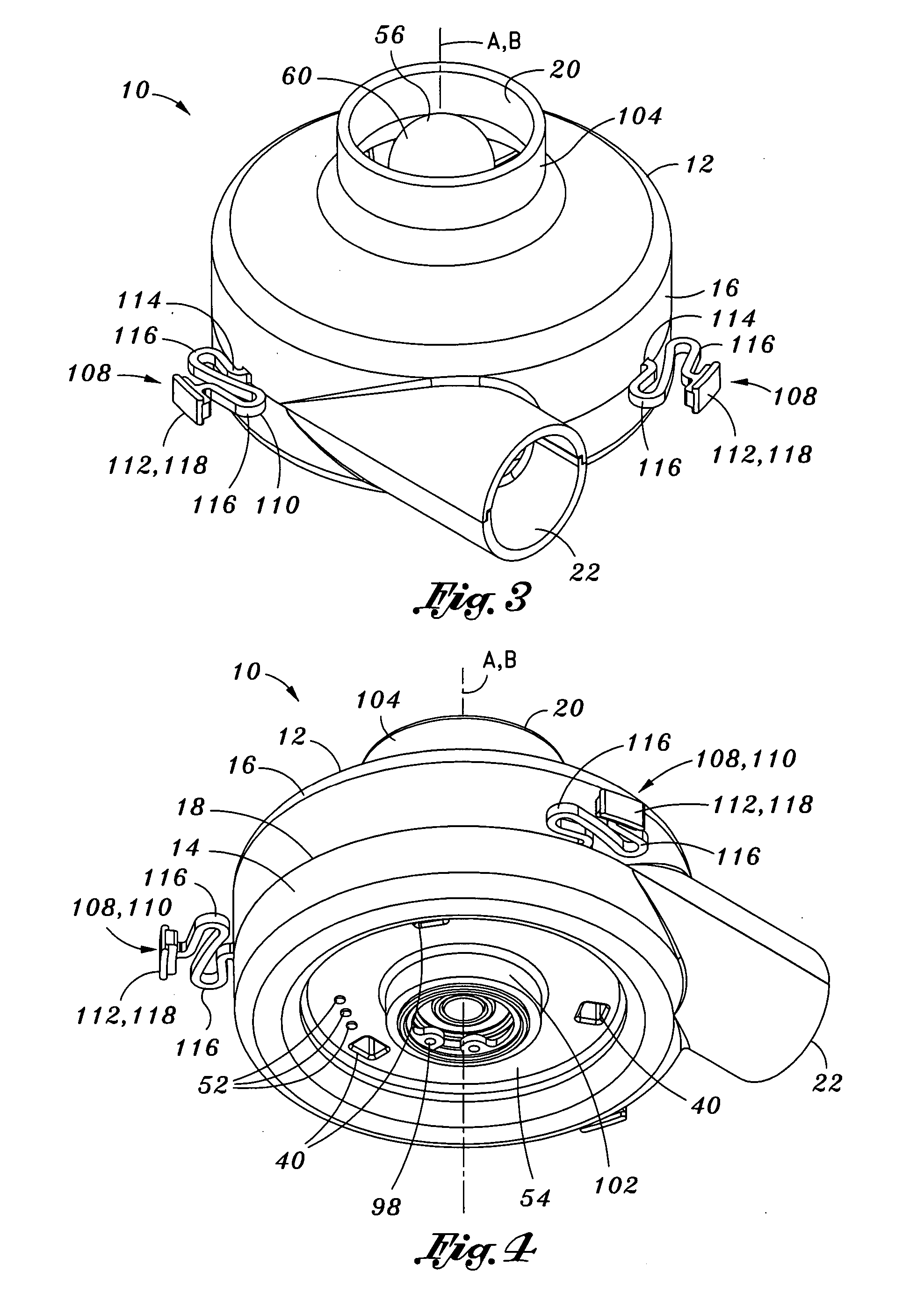
[0036] Referring now to the drawings wherein the showings are for purposes of illustrating preferred embodiments of the present invention and not for purposes of limiting the same, shown in FIGS. 1-10 is a blower assembly 10 which is specifically configured to provide a relatively high flow rate at relatively high pressure while consuming relatively little input power. The blower assembly 10 is configured in a relatively small size having a short axial height small diameter but which is capable of producing a relatively high flow rate of compressed with minimal output of vibration, noise and heat. In this regard, the blower assembly 10 is particularly well-suited for use in sensitive applications such as in a portable or wearable continuous positive airway pressure (CPAP) device similar to that which is disclosed in U.S. application Ser. No. 11 / 649,674 entitled User Interface and Headgear for a Continuous Positive Airway Pressure Device, the entire contents of which is incorporated ...


PUM


Abstract

A blower assembly comprises a blower housing having a stator assembly integrally formed therewith. The stator assembly includes a stator bore having a rotor magnet rotatable therewithin such that the motor assembly is configured as a brushless D.C. motor. An impeller is mounted on a motor shaft of the motor assembly and has a plurality of vanes extending upwardly therefrom. Each one of the vanes has a vane height which is optimized to minimize the formation of fluid eddy losses during compression of air by the impeller. A bearing assembly rotatably coupling the rotor magnet to the stator assembly is sized and configured to maintain an air gap of approximately 0.0002 inches between the vanes and a housing interior surface of the blower housing during rotation of the impeller.

Description

CROSS-REFERENCE TO RELATED APPLICATIONS [0001] The present application claims priority to U.S. Provisional Application No. 60 / 793,433 filed on Apr. 20, 2006, the entire contents of which is expressly incorporated by reference herein. The present application is also related to U.S. Utility patent application Ser. No. 11 / 128,552 entitled PORTABLE CONTINUOUS POSITIVE AIRWAY PRESSURE SYSTEM filed on May 13, 2005, and to U.S. Utility patent application Ser. No. 11 / 649,674 entitled USER INTERFACE AND HEAD GEAR FOR A CONTINUOUS POSITIVE AIRWAY PRESSURE DEVICE filed on Jan. 4, 2007, the entire contents of each being expressly incorporated by reference herein. STATEMENT RE: FEDERALLY SPONSORED RESEARCH / DEVELOPMENT [0002] (Not Applicable)BACKGROUND [0003] The present invention relates generally to patient ventilation systems and, more particularly, to a motor blower assembly incorporating an improved brushless D.C. motor assembly of reduced size and which is configured to rotatably drive a pr...

Claims


Application Information

Patent Timeline
IPC IPC(8): H02K1/04H02K5/24H02K5/00
CPCF04D25/0606H02K5/1732A61M2205/42H02K7/14A61M16/0066H02K5/24F04D29/668
Inventor HOFFMAN, LESLIELATHROP, RAYMOND
Owner VYAIRE MEDICAL 211 INC
Why Eureka
Try Eureka