Hybrid Capacitive Touch Screen Element

a capacitive touch and touch screen technology, applied in the direction of instruments, electric digital data processing, input/output process of data processing, etc., can solve the problems of increasing construction costs, reducing transparency, and difficulty in scaling up the screen size, and achieves low power consumption, high reliability, and simple wiring requirements

Active Publication Date: 2007-10-25
NEODRON LTD
View PDF22 Cites 265 Cited by
  • Summary
  • Abstract
  • Description
  • Claims
  • Application Information

AI Technical Summary

Benefits of technology

[0019]The present invention is similar to my earlier co-pending application U.S. Ser. No. 10 / 916,759 published as US 2005 / 0041018 A1 in that it also comprises two bus-bars on two of the four possible sides of the element, and has a central sensing region which exhibits anisotropic properties. However, the present invention is an improvement on the teaching of patent application U.S. Ser. No. 10 / 916,759 published as US 2005 / 0041018 A1 by means of a new pattern within the sensing region that avoids cross-conduction between the bus-bars. Advantageously, the sensing element of the invention eliminates pin-cushion distortion entirely or almost completely.

Problems solved by technology

However, this scheme requires numerous secondary electrode connections as well as two or more layers of construction, increasing construction costs and reducing transparency.
However this patent suffers from the problem that it is difficult to scale up the screen size, as the number of electrode connections to a sensing circuit is one per triangle.
Many types of 2DCT are known to suffer from geometric distortion characterized as ‘pin cushion’ or ‘hyperbolic’ or ‘parabolic’, whereby the reported coordinate of touch is in error due to electrical effects on the sensing surface.
However, this design offers limited resolution for the 2DCT.

Method used


Image

  • Hybrid Capacitive Touch Screen Element
  • Hybrid Capacitive Touch Screen Element
  • Hybrid Capacitive Touch Screen Element

Examples


Embodiment Construction

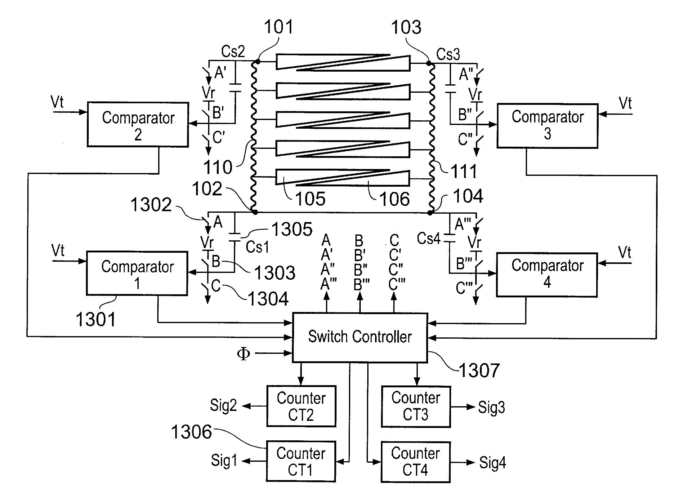
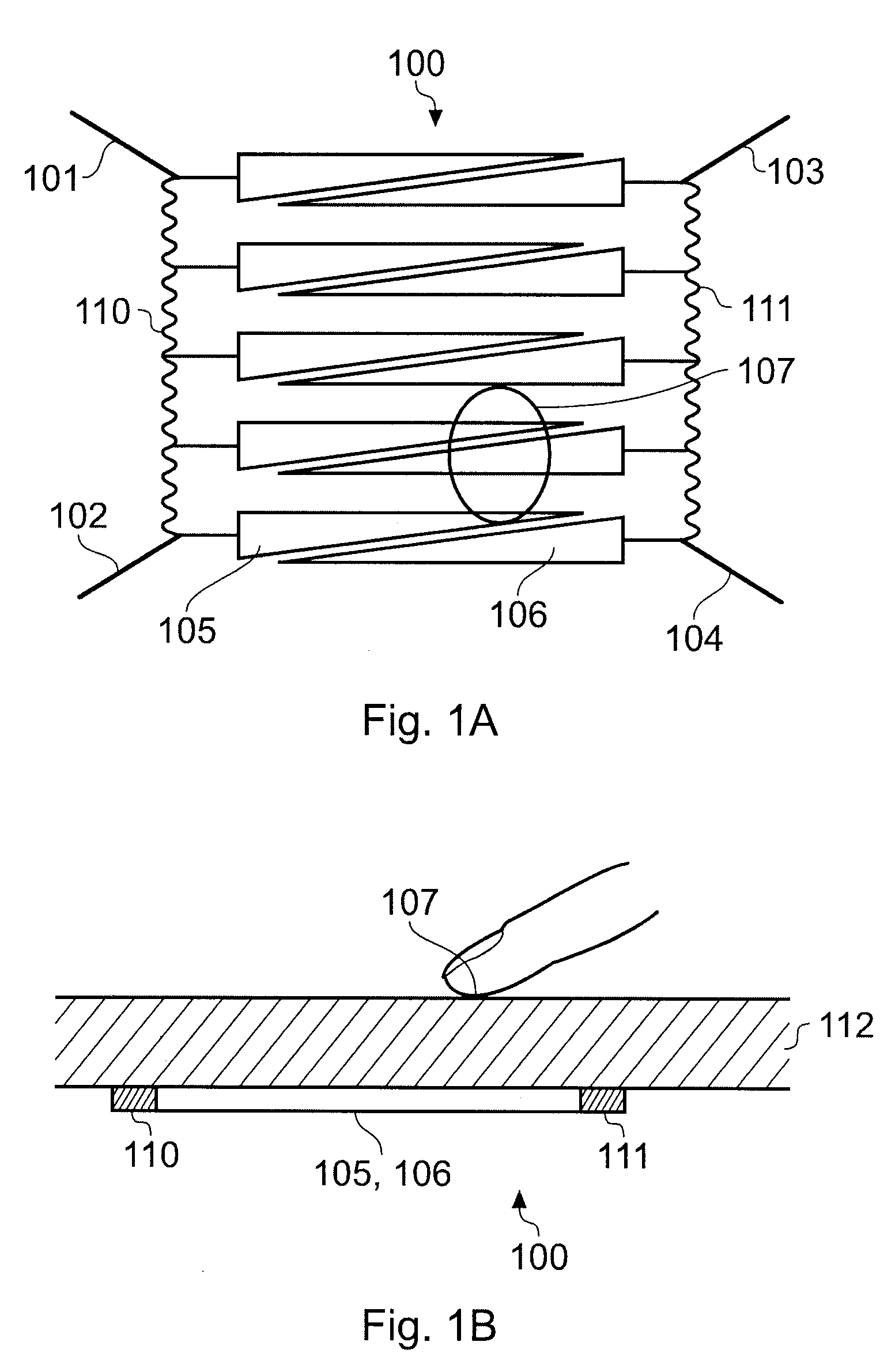
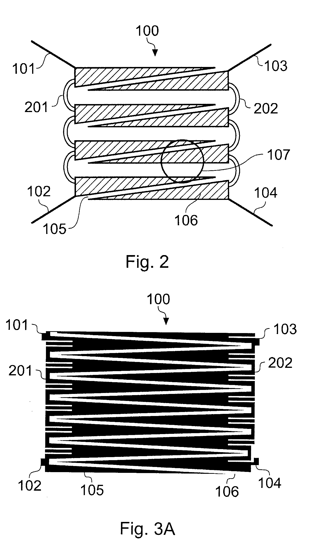
[0052]Referring to the drawings, FIGS. 1a, 1b illustrate a 2DCT sensing element 100 embodying the invention with four connection electrodes 101, 102, 103, 104 at respective corners of the sensing element. The electrodes 101-104 are connected to a sensing circuit (not shown). On the left and right sides of the sensing element 100 are shown respective resistive elements 110, 111 which connect between electrodes 101 and 102 and electrodes 103 and 104 respectively. Within the sensing region are two distinct sets of triangulated conductive shapes, one set 105 being connected to resistive side 110 and the other set 106 connected to resistive side 111. The triangulated shapes are interleaved so as to provide a left-right field gradient; in use, a finger running from the left side to the right side of the sensing element would naturally induce a capacitance gradation which can be measured on electrodes 101-104 in such a way as to allow a determination of horizontal position using ratiometri...


PUM


Abstract

A capacitive touch sensitive position sensor is provided which has a substrate defining a touch sensitive platform. First and second resistive bus-bars arranged spaced apart on the substrate. A conductive sensing area is formed between the bus bars and is constructed with first and second conductive elements connected to the first and second resistive bus-bars respectively, and spaced apart from each other by non-conducting gaps, so that currents induced in the conductive sensing area flow towards the bus-bars, but are prevented from flowing in a direction parallel to the bus-bars. This design removes pin-cushion distortion and enhances linearization of the output signals. Because the sensing region is not galvanically coupled from one bus bar to the other, the voltage gradients remain uniform and undistorted. Capacitive coupling from one side to the other does not produce a distortion component provided that the capacitance is allowed to fully charge and discharge across all locations in the sensing region.

Description

[0001]This invention claims priority from U.S. provisional application 60 / 745,583 filed on 25 Apr. 2006. Co-pending application U.S. Ser. No. 10 / 916,759, published as US 2005 / 0041018 A1 is incorporated by reference herein.BACKGROUND OF THE INVENTION[0002]The invention pertains to 2-dimensional touch sensing surfaces operable by a human finger, or a stylus. Example devices include touch screens and touch pads, particularly those over LCDs, CRTs and other types of displays, or pen-input tablets, or encoders used in machinery for feedback control purposes.[0003]In my earlier co-pending U.S. application Ser. No. 10 / 916,759, published as US 2005 / 0041018 A1, I describe a pattern of conductors which have anisotropic galvanic properties within the sensing region, due to the use of conductive stripes which prevent current flows in more than one direction, or possibly through the use of a special anisotropic conductive material which can be unpatterned. At least four electrodes are connected,...

Claims


Application Information

Patent Timeline
Patent Type & Authority Applications(United States)
IPC IPC(8): G06F3/041
CPCG06F3/045G06F3/044G06F3/04166G06F3/0443G06F2203/04103G06F3/0448
Inventor PHILIPP, HARALD
Owner NEODRON LTD
Why Eureka
Try Eureka