Active-clamp current-source push-pull dc-dc converter

a technology of push-pull dc-dc converter and current-source push-pull, which is applied in the direction of dc-dc conversion, climate sustainability, power conversion systems, etc., can solve the problems of reducing the power conversion efficiency of the converter, and the difficulty of the conventional current-source push-pull dc-dc converter to operate for a wide input range, so as to reduce the stress of the switch voltage. , to achieve the effect of increasing the converter

Inactive Publication Date: 2007-10-25
POSTECH ACAD IND FOUND
View PDF5 Cites 198 Cited by
  • Summary
  • Abstract
  • Description
  • Claims
  • Application Information

AI Technical Summary

Benefits of technology

[0008]The present invention also provides a current-source push-pull DC-DC converter using an active clamp circuit for increasing a power conversion efficiency of the converter even for a wide input voltage range and reducing a switch voltage stress as compared to a conventional current-source push-pull circuit by operating even for a duty ratio below 0.5 by flowing a current of an input inductor through capacitors of the active clamp circuit when both main switches are off.

Problems solved by technology

Thus, a range of the use of the duty ratio is narrow, and thereby, a maximum voltage over the switches S1 and S2 is higher than the maximum input voltage, and it is difficult for the conventional current-source push-pull DC-DC converter to operate for wide input range.
In addition, a passive snubber circuit mainly used to prevent a switching component from being damaged due to energy stored in a leakage inductance of the transformer T1 reduces the converter power conversion efficiency.

Method used


Image

  • Active-clamp current-source push-pull dc-dc converter
  • Active-clamp current-source push-pull dc-dc converter
  • Active-clamp current-source push-pull dc-dc converter

Examples


Embodiment Construction

[0018]The present invention will now be described more fully with reference to the accompanying drawings, in which exemplary embodiments of the invention are shown. In the following description, well-known functions or constructions are not described in detail since they would obscure the invention in unnecessary detail. However, the terminology described below is defined considering functions in the present invention and may vary according to a user or application. Thus, the definitions should be understood based on all the contents of the specification.

[0019]In the description below, if the elements in the present invention are the same as elements in the prior art, reference numerals used in the prior art are used as present in the prior art, and their detailed description is omitted.

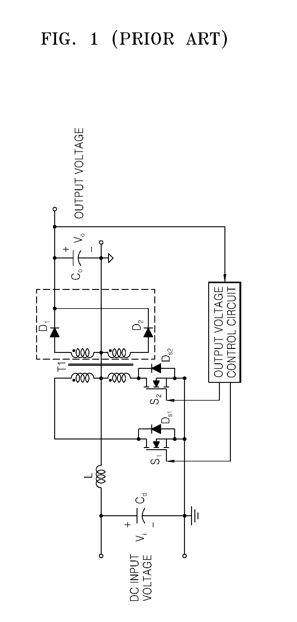
[0020]FIG. 1 is a circuit diagram of a conventional current-source push-pull DC-DC converter.

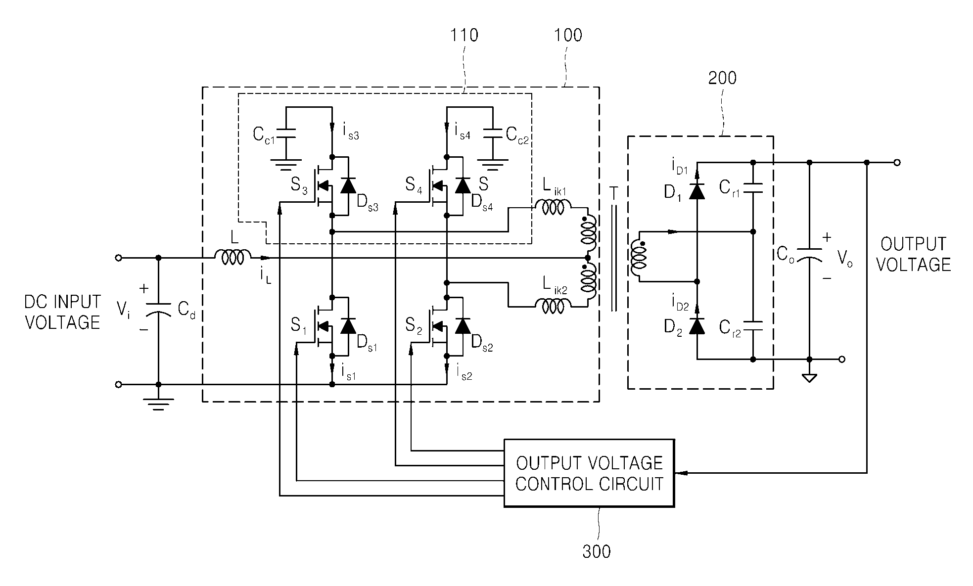
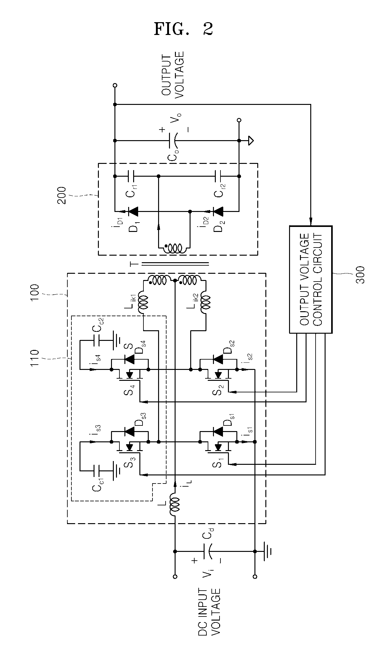
[0021]Referring to FIG. 1, the active-clamp current-source push-pull DC-DC converter according to the pres...


PUM


Abstract

Provided is a current-source push-pull DC-DC converter using an active clamp circuit for reusing energy of leakage inductances by not only diodes on a secondary side of a transformer being zero-current switched using a series-resonant full-wave rectifier, but also the active clamp circuit on a primary side of the transformer, which provides a discharge path of the energy stored in the leakage inductances, increases power conversion efficiency even for a wide input voltage range and reduces a switch voltage stress as compared to a conventional current-source push-pull circuit by operating even for a duty ratio below 0.5 by flowing a current of an input inductor through capacitors of the active clamp circuit when both main switches are off.

Description

CROSS-REFERENCE TO RELATED PATENT APPLICATION[0001]This application claims the benefit of Korean Patent Application No. 10-2006-0035324, filed on Apr. 19, 2006, in the Korean Intellectual Property Office, the disclosure of which is incorporated herein in its entirety by reference.1. FIELD OF THE INVENTION[0002]The present invention relates to an active-clamp current-source push-pull DC-DC converter, and more particularly, to a current-source push-pull DC-DC converter comprising the diodes on a secondary side of a transformer to be zero-current switched using a series-resonant full-wave rectifier, and the active clamp circuit on a primary side of the transformer providing a discharge path of the energy stored in the leakage inductances to reuse energy of leakage inductance.[0003]The present invention also relates to an active-clamp current-source push-pull DC-DC converter increasing the power conversion efficiency of the current-source push-pull DC-DC converter even for a wide input ...

Claims


Application Information

Patent Timeline
Patent Type & Authority Applications(United States)
IPC IPC(8): H02M3/335
CPCH02M3/33569Y02B70/1433H02M3/3372Y02B70/10H02M3/01H02M3/325
Inventor KWON, BONG HWANKWON, JUNG MIN
Owner POSTECH ACAD IND FOUND
Why Eureka
Try Eureka