Wireless Transmission System, Wireless Station Used Therein and Method Used Therefor

a wireless transmission system and wireless transmission technology, applied in the field of wireless transmission systems, can solve the problems of multipath fading, transmission characteristics will significantly deteriorate, and the effect of path diversity cannot be obtained

Active Publication Date: 2007-10-25
PANASONIC INTELLECTUAL PROPERTY CORP OF AMERICA
View PDF3 Cites 27 Cited by
  • Summary
  • Abstract
  • Description
  • Claims
  • Application Information

AI Technical Summary

Benefits of technology

[0084] As mentioned above, the present invention provides, in the multi-station simultaneous transmission system in which the plurality of wireless stations arranged adjacently to each other transmit the same data, even when the relative position between the wireless stations or the number of wireless stations for performing the multi-station simultaneous transmission of the data is changed, the wireless transmission system which can certainly obtain the effect due to the path diversity, the wireless station used therein, and the method used therefore.

Problems solved by technology

Generally, in a wireless communication, transmitted signals arrive at a receiver at different propagation times via a plurality of propagation paths, thus causing multipath fading.
Even in such a multi-station system, however, the effect due to the path diversity cannot be obtained at a point where the TDOA between incoming waves from respective antennas deviate from a range which is equal to or more than the above-mentioned delay resolution and equal to or more than above-mentioned maximum delay.
On the contrary, for example, when the TDOA between the incoming waves from two stations is extremely short, since the signals cancel each other at a point where two delayed waves with equal power are simultaneously received with opposite phases, the transmission characteristics will deteriorate significantly.
Meanwhile, even in a point where the TDOA between the incoming waves from two stations exceeds the maximum delay, not only the path diversity effect is not obtained, but also the transmission characteristics will deteriorate.

Method used


Image

  • Wireless Transmission System, Wireless Station Used Therein and Method Used Therefor
  • Wireless Transmission System, Wireless Station Used Therein and Method Used Therefor
  • Wireless Transmission System, Wireless Station Used Therein and Method Used Therefor

Examples


first embodiment

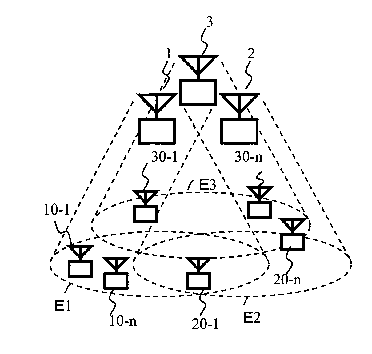
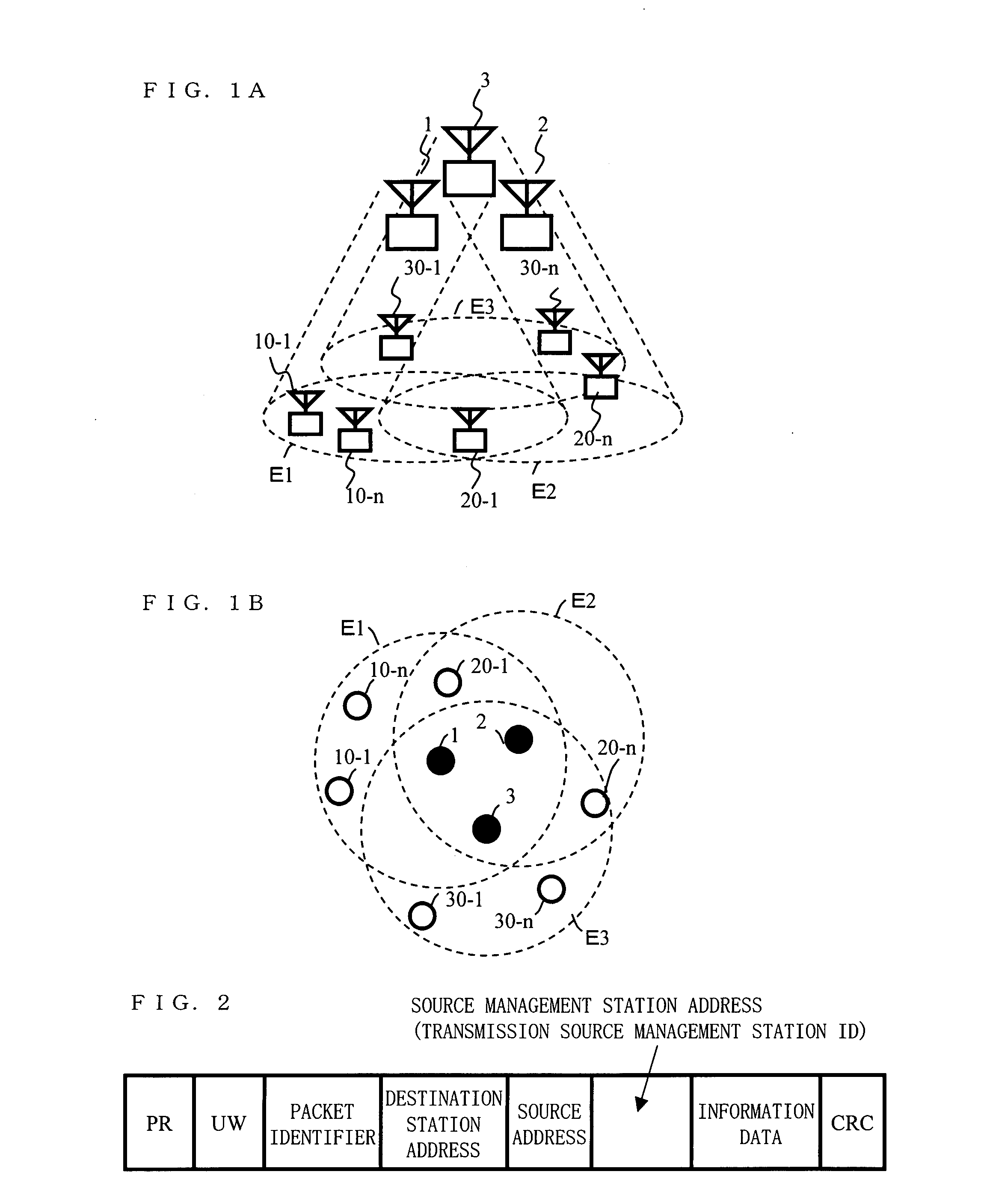
[0250]FIG. 1A is a diagram illustrating an example of a configuration of a wireless transmission system according to a first embodiment of the present invention. In FIG. 1A, the wireless transmission system is provided with management stations 1 through 3, each being a wireless station, and terminal stations 10-1 through 10-n, 20-1 through 20-n, and 30-1 through 30-n, each being a wireless station. FIG. 1B is a diagram illustrating a relative position between the management stations 1 through 3 and the terminal stations shown in FIG. 1A.

[0251] The management stations 1 through 3 form communication areas E1 through E3, respectively, and are connected with the terminal stations existing within respective communication areas with wireless. The management stations 1 through 3 perform channel assignment or the like for the terminal stations existing within respective communication areas. Incidentally, the communication areas E1 through E3 indicate communication areas when the management...

second embodiment

[0373] The wireless transmission system in accordance with the present embodiment is different from the first embodiment in that after the management station transmits a packet, when other management stations relay-transmit the packet, the management station being the source station also transmits the same packet again.

[0374]FIGS. 26A and B are diagrams illustrating examples of the multihop transmission in the second embodiment. As shown in FIGS. 26A and B, the management station 1 being the source management station, after transmitting a packet to be relay-transmitted to the management stations 2 and 3, retransmits this packet again to the destination station. Note herein that since a configuration of the wireless transmission system and the management station in accordance with the present embodiment is similar to that of the first embodiment, FIGS. 1A, B, and FIG. 5 will be used, respectively.

[0375] In the present embodiment, the management station which relay-transmits the pac...

third embodiment

[0394] The wireless transmission system in accordance with a third embodiment is different from the second embodiment in that the delay amount given to the packet that the source management station capable of performing the multi-station simultaneous transmission relay-transmits during the relay transmission is decided to be a value properly shifted from the reference timing (T0) in advance. The configuration of the wireless transmission system and the management station, and the negotiation procedure of the channel information between the systems other than that are similar to those of the first embodiment and the second embodiment.

[0395]FIG. 30A is a diagram illustrating an example of the negotiation procedure in the third embodiment from the system configuration shown in FIG. 16A where one wireless system is generated to the system configuration shown in FIG. 16B. The management station in accordance with the present embodiment is different from that shown in FIG. 27B (the secon...


PUM


Abstract

A wireless transmission system capable of performing a multi-station simultaneous transmission of data, that is, simultaneously transmitting data by wireless to a plurality of stations. The wireless transmission system includes a plurality of wireless stations for transmitting / receiving data and it constitutes a system for path diversity by use of a wireless station at the transmitting end, a multipath transmission path, and a wireless station at the receiving end. At least one of the plurality of wireless stations decides, in accordance with a response packet responsive to a multi-station simultaneous transmission request packet transmitted by the wireless station or other stations, a plurality of delay amounts relative to a reference timing during the multi-station simultaneous transmission in the wireless transmission system. It is arranged that each difference between the plurality of delay amounts be greater than a predetermined delay resolution and that the difference between the maximum and minimum values in the plurality of delay amounts be smaller than a predetermined maximum delay.

Description

TECHNICAL FIELD [0001] The present invention relates to a wireless transmission system in which a plurality of wireless stations transmit data, a wireless station used therein, and a method used therefore, and relates more specifically to a wireless transmission system in which a plurality of wireless stations which are adjacent to each other perform a multi-station simultaneous transmission of data, a wireless station used therein and a method therefore. BACKGROUND ART [0002] Generally, in a wireless communication, transmitted signals arrive at a receiver at different propagation times via a plurality of propagation paths, thus causing multipath fading. In order to prevent deterioration of transmission characteristics due to the multipath fading, a modulation / demodulation scheme having an anti-multipath characteristic is used. [0003] The modulation / demodulation scheme having the anti-multipath characteristic includes, for example, a spectrum spread scheme, an OFDM (OFDM; Orthogonal...

Claims


Application Information

Patent Timeline
Patent Type & Authority Applications(United States)
IPC IPC(8): H04Q7/00H04W84/18
CPCH04W84/18H04B7/022
Inventor YAMASAKI, HIDETOSHITAKAI, HITOSHINAKAHARA, HIDEKIMIYANAGA, KENJI
Owner PANASONIC INTELLECTUAL PROPERTY CORP OF AMERICA
Why Eureka
Try Eureka