
Light amount adjuster and imaging apparatus

Inactive Publication Date: 2007-10-25
SONY CORP
View PDF5 Cites 21 Cited by
  • Summary
  • Abstract
  • Description
  • Claims
  • Application Information

AI Technical Summary

Benefits of technology

[0014]When the apparatus described in JP-A-2003-241253 is applied to a video camcorder using a color separation prism, it can be expected that insertion and removal of the ND filters to and from the aperture from opposite directions can provide an effect of preventing color unevenness. However, the transparent region surrounded by the two ND regions forms a slit-like aperture in some cases, resulting in more significant degradation due to diffraction than the degradation experienced in the apparatuses described in JP-A-6-265971 and JP-A-2004-205951. Additionally, it is anticipated that degradation in image quality due to phase difference of the wavefronts that pass the boundary between the transparent region and the ND region will also be significant.
[0015]In view of the above problems, it is desirable to provide a light amount adjuster capable of preventing diffraction caused by a stopped-down aperture stop and an imaging apparatus having such a light amount adjuster.
[0018]According to the invention, it is possible to prevent diffraction caused by a small aperture size of the aperture stop.

Problems solved by technology

Considering an imaging apparatus as a video camcorder for imaging moving pictures, the proposals described above have various problems when implemented.
However, insertion and removal of the ND filters to and from the light path affects the moving picture screen, resulting in unnatural reproduced images.
However, changing the F-number of the aperture stop for exposure adjustment will not be carried out fast enough to be synchronized with the change in ND density, resulting in recording of a bright screen at one instant and a dark screen at another instant.
At present, however, there are a large number of problems resulting from material and manufacturing methods, such as the non-flat spectral transmittance characteristic in the visible light region, slow response to the applied voltage, insufficient light adjustment range between the highest transmittance and the highest density, poor durability, and temperature dependence and aging property of the above characteristics.
Therefore, the performance of the apparatuses is far from applicable to video camcorders.

Method used


Image

  • Light amount adjuster and imaging apparatus
  • Light amount adjuster and imaging apparatus
  • Light amount adjuster and imaging apparatus

Examples


first embodiment

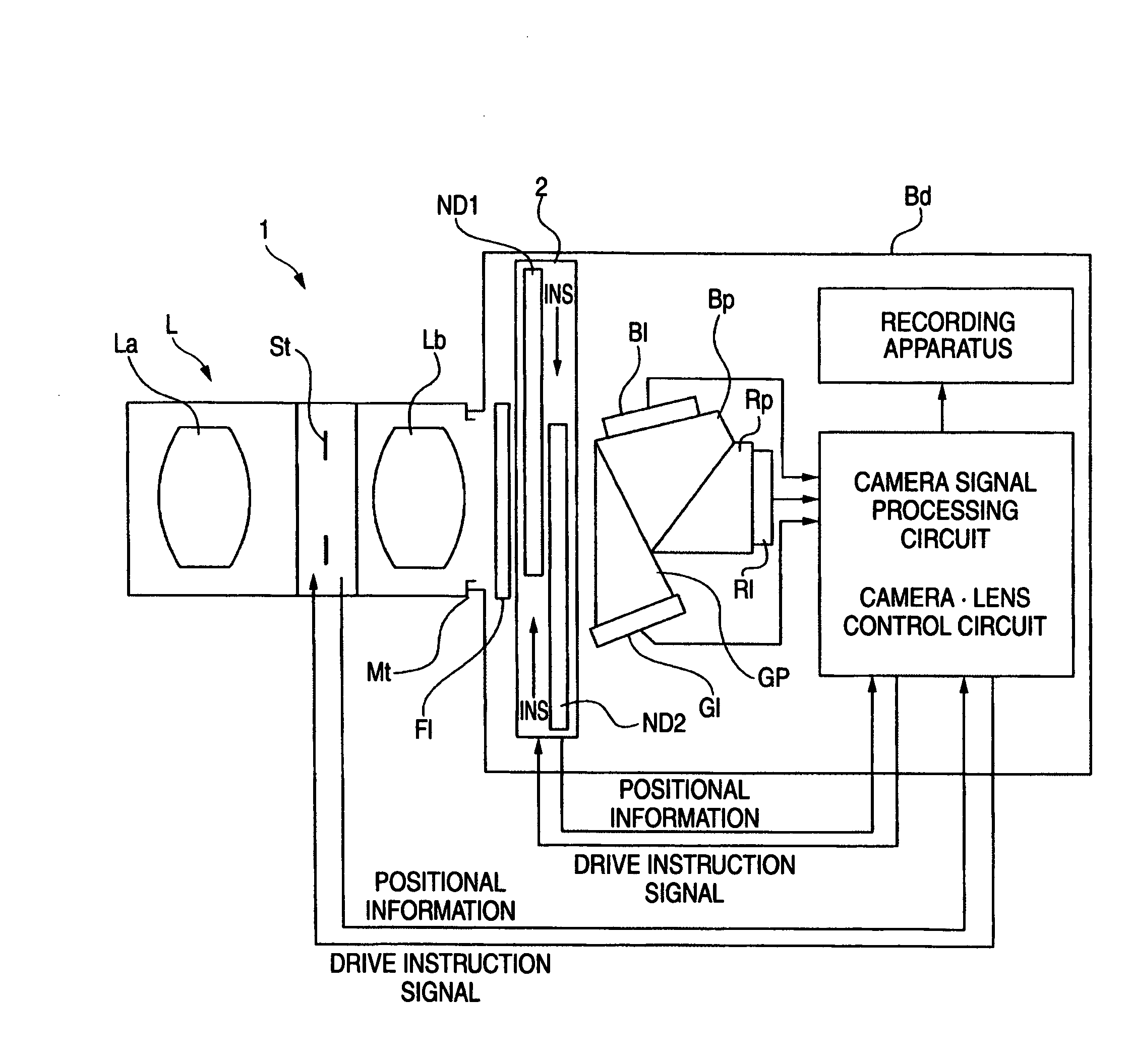
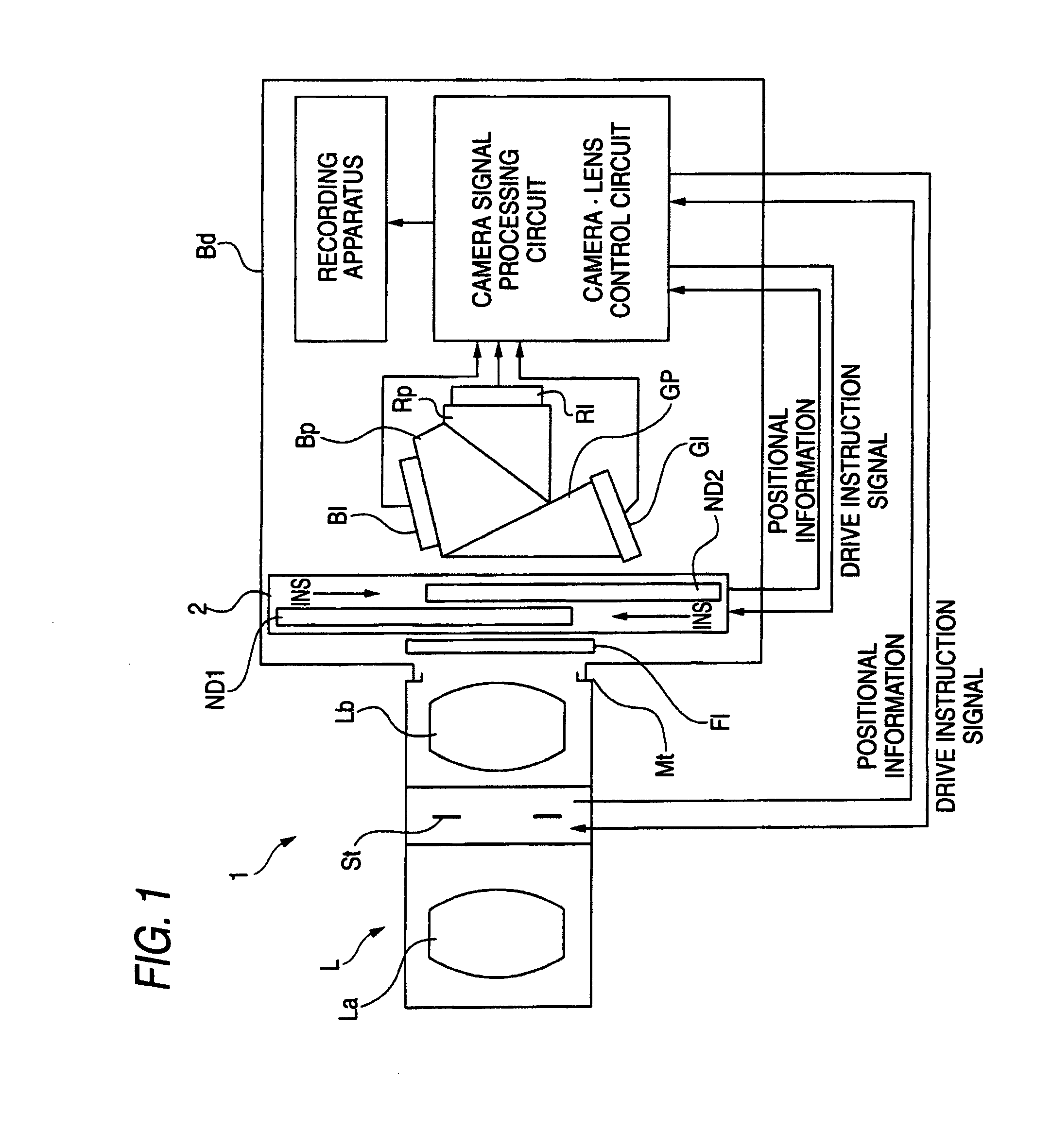
[0063]FIG. 1 schematically shows the imaging apparatus according to the invention.

[0064]The imaging apparatus 1 includes a lens L, a light amount adjuster 2 and imaging devices GI, BI and RI. The light amount adjuster 2 includes two filter members ND1 and ND2 disposed such that they face each other and can symmetrically move with respect to each other, each of the filter members having a gradation ND region where the transmittance continuously changes and a transparent region where the transmittance is uniform and at least 80%. The light amount adjuster 2 is also configured such that in order to provide the highest transmittance, the transparent regions of the two filter members overlap each other and cover the entire light path, while in order to limit the amount of transmitted light, the gradation ND regions are symmetrically inserted into the light path from opposite positions in such a way that the ND density of the gradation ND region in the light path gradually increases so as...

second embodiment

[0081]FIG. 7 shows filter members aND1 and aND2 used in the light amount adjuster 2. Each of the filter members aND1 and aND2 has a gradation ND region gnd where the transmittance continuously changes and a lowest density region lnd where the transmittance is uniform and 80% or lower.

[0082]In the light amount adjuster 2 using the filter members aND1 and aND2, the two filter members aND1 and aND2 are disposed such that they face each other and can symmetrically move with respect to each other. To provide the highest transmittance, the two filter members aND1 and aND2 are both retracted from the light path LD. To limit the amount of transmitted light, one or both of the lowest density regions lnd of the filter members aND1 and aND2 are inserted into the light path LD and cover the entire light path LD, and then, the gradation ND regions gnd are symmetrically inserted into the light path from opposite positions in such a way that the ND density of the gradation ND region gnd in the li...

third embodiment

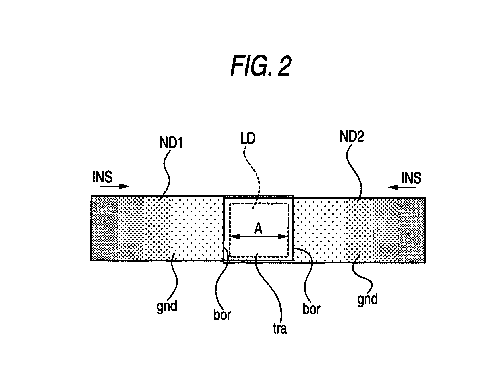
[0090]FIG. 11 shows filter members bND1 and bND2 used in the light amount adjuster 2. Each of the filter members bND1 and bND2 has a gradation ND region gnd where the transmittance continuously changes, a lowest density region lnd where the transmittance is uniform and 80% or lower and a transparent region tra where the transmittance is uniform and at least 80%.

[0091]In the light amount adjuster 2 using the filter members bND1 and bND2, the two filter members bND1 and bND2 are disposed such that they face each other and can symmetrically move with respect to each other. To provide the highest transmittance, the transparent regions tra of the two filter members bND1 and bND2 overlap each other and cover the entire light path LD. To limit the amount of transmitted light, one or both of the lowest density regions lnd of the filter members bND1 and bND2 are inserted into the light path LD and cover the entire light path LD, and then, the gradation ND regions gnd are symmetrically inser...


PUM


Abstract

A light amount adjuster includes two filter members, each having a gradation ND region where the transmittance continuously changes, disposed such that the two filter members face each other and the direction in which the gradation of one of the filter members changes differs from the direction in which the gradation of the other one of the filter members changes and configured such that the filter members can move in a symmetrical manner with respect to each other.

Description

CROSS REFERENCES TO RELATED APPLICATIONS[0001]The present invention contains subject matter related to Japanese Patent Application JP 2006-117463 filed in the Japanese Patent Office on Apr. 21, 2006, the entire contents of which being incorporated herein by reference.BACKGROUND OF THE INVENTION[0002]1. Field of the Invention[0003]The present invention relates to a novel light amount adjuster and imaging apparatus. More particularly, the invention relates to a light amount adjuster that causes little degradation in image quality and is suitable for a camera that uses an imaging device to receive light, such as a video camcorder and a digital still camera, and an imaging apparatus having such a light amount adjuster.[0004]2. Description of the Related Art[0005]An aperture stop is generally used as means for adjusting the amount of incident light in an imaging apparatus. However, it has been pointed out for a long time that a small aperture size (a large F-number) disadvantageously res...

Claims


Application Information

Patent Timeline
IPC IPC(8): G02B5/22G03B7/00G02B5/00G03B7/18G03B9/02G03B11/00H04N5/235H04N5/238H04N101/00
CPCG02B26/02G03B7/18H04N5/238G03B11/00H04N5/2254G03B9/02H04N23/55H04N23/75
Inventor NANJO, YUSUKE
Owner SONY CORP
Learn More