Developing apparatus, process cartridge, image forming apparatus, and assemblying method for developing apparatus

a development apparatus and process cartridge technology, applied in the direction of electrographic process apparatus, optics, instruments, etc., can solve the problems of excessive force applied to the developing means frame, unnecessary large amount of force applied from the development roller to the photosensitive drum, etc., to simplify the method of assembling

Active Publication Date: 2007-10-25
CANON KK
View PDF7 Cites 13 Cited by
  • Summary
  • Abstract
  • Description
  • Claims
  • Application Information

AI Technical Summary

Benefits of technology

[0013]Another object of the present invention is to simplify the method for assembling the above described process cartridge.
[0014]According to an aspect of the present invention, there is provided a developing apparatus usable with an electrophotographic image forming apparatus for forming an image on a recording material, said developing apparatus comprising a developer carrying member for developing a latent image formed on an electrophotographic photosensitive member with a developer; a first frame for accommodating the developer, said first frame including a first opening for supplying the developer and a first connecting portion provided around first opening; a second frame containing said developer carrying member, a second opening for receiving supply of the developer from said first opening and a second connecting portion provided around said second opening; an elastomer for connecting said first connecting portion and said second connecting portion with each other with said first opening and said second opening being opposed to each other so as to permit movement of said first frame and said second frame and so as to prevent the developer from leaking between said first connecting portion and said second connecting portion.
[0015]According to another aspect of the present invention, there is provided a developing apparatus usable w

Problems solved by technology

However, in order to ensure that the abovementioned joint remains perfectly sealed with the use of the above described prior art, the foamed urethane seal must be compressed by a large amount, making it possible th

Method used


Image

  • Developing apparatus, process cartridge, image forming apparatus, and assemblying method for developing apparatus
  • Developing apparatus, process cartridge, image forming apparatus, and assemblying method for developing apparatus
  • Developing apparatus, process cartridge, image forming apparatus, and assemblying method for developing apparatus

Examples


embodiment 1

(1) Structure of Entirety of Electrophotographic Image Forming Apparatus

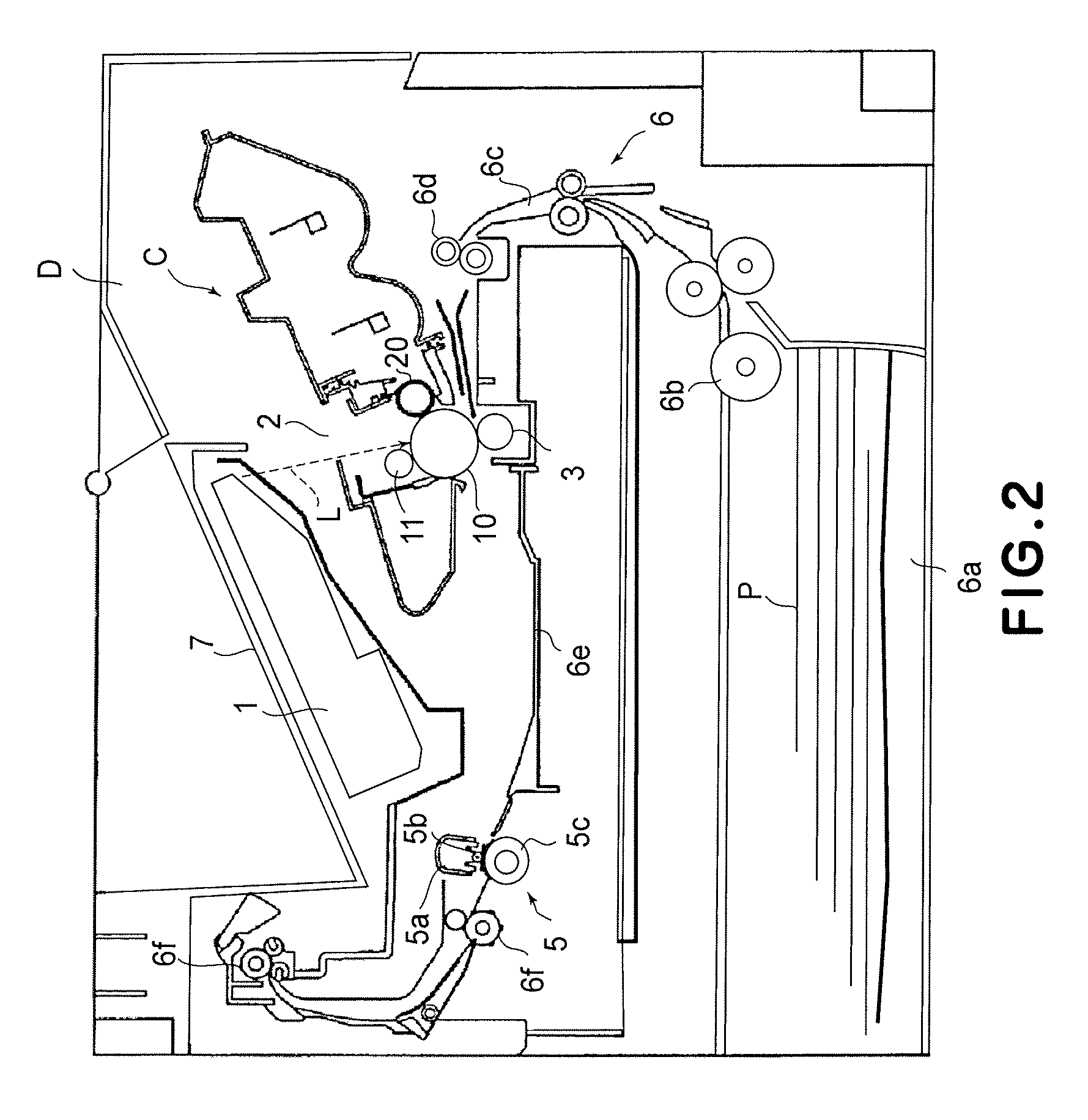
[0064]FIG. 2 is a schematic drawing of an example of an electrophotographic image forming apparatus, showing the general structure thereof. This electrophotographic image forming apparatus (which hereafter will be referred to simply as image forming apparatus) is a laser printer which forms an image on recording medium (for example, recording paper, OHP sheet, fabric, etc.) with the use of an electrophotographic process.

[0065]In the image forming apparatus, an electrophotographic photosensitive member in the form of a drum 10 (which hereafter will be referred to as “photosensitive drum”) is rotated in the direction indicated by an arrow mark at a preset peripheral velocity (process speed). The peripheral surface (surface) of the photosensitive drum 10 is uniformly charged by a charging means 11. The charged area of the peripheral surface of the photosensitive drum 10 is exposed to a beam of laser light L project...

embodiment 2

[0108]Next, the development unit in another embodiment of the present invention will be described.

[0109]The components in this embodiment, which are identical to those in the first embodiment will be given the same referential symbols as those given to the counterparts in the first embodiment, and will not be described in order not to repeat the same descriptions. Like the development unit A in the first embodiment, the development unit A in this embodiment also is integrally joined with the photosensitive member unit B to make up the cartridge C, and so is the cartridge C in the third embodiment.

[0110]FIG. 17 is a drawing of the developer storage frame 61 and a developer storage frame sealing member 19 (which hereafter will be referred to simply as sealing member) before the sealing member 19 is attached to the developer storage frame 61. FIG. 18 is a drawing of the developer storage frame 61 and a developer storage frame sealing member 19 after the sealing member 19 was attached t...

embodiment 3

[0118]Next, the development unit in another embodiment of the present invention will be described.

[0119]FIG. 22 is a perspective view of the developing means frame 51 as seen from the developer storage frame 61 side. FIG. 23 is a perspective view of he developer storage frame 61 as seen from the developing means frame 51 side. FIG. 24 is a perspective view of the developer storage frame 61 prior to the attachment of the elastic sealing members 81, 82, 83, and 84 to the developer storage frame 61. FIG. 25 is a perspective view of the developer storage frame 61 after the attachment of the elastic sealing members 81, 82, 83, and 84 to the developer storage frame 61. FIG. 26 is a perspective view of the developing means frame 51 and developer storage frame 61, which have been joined by their flanges 51d and 61b.

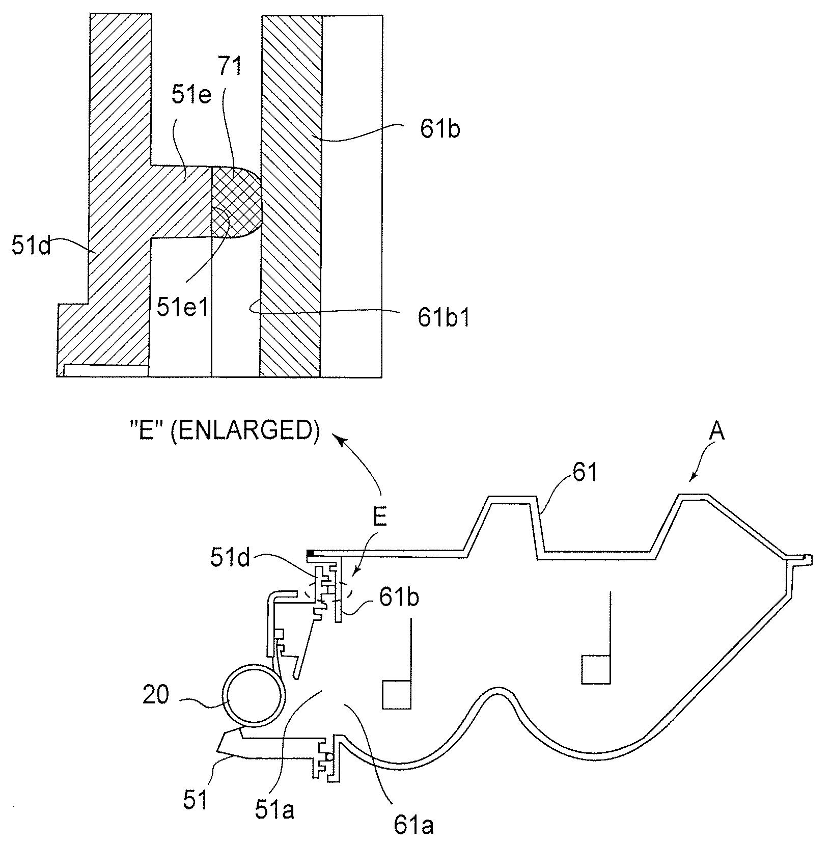
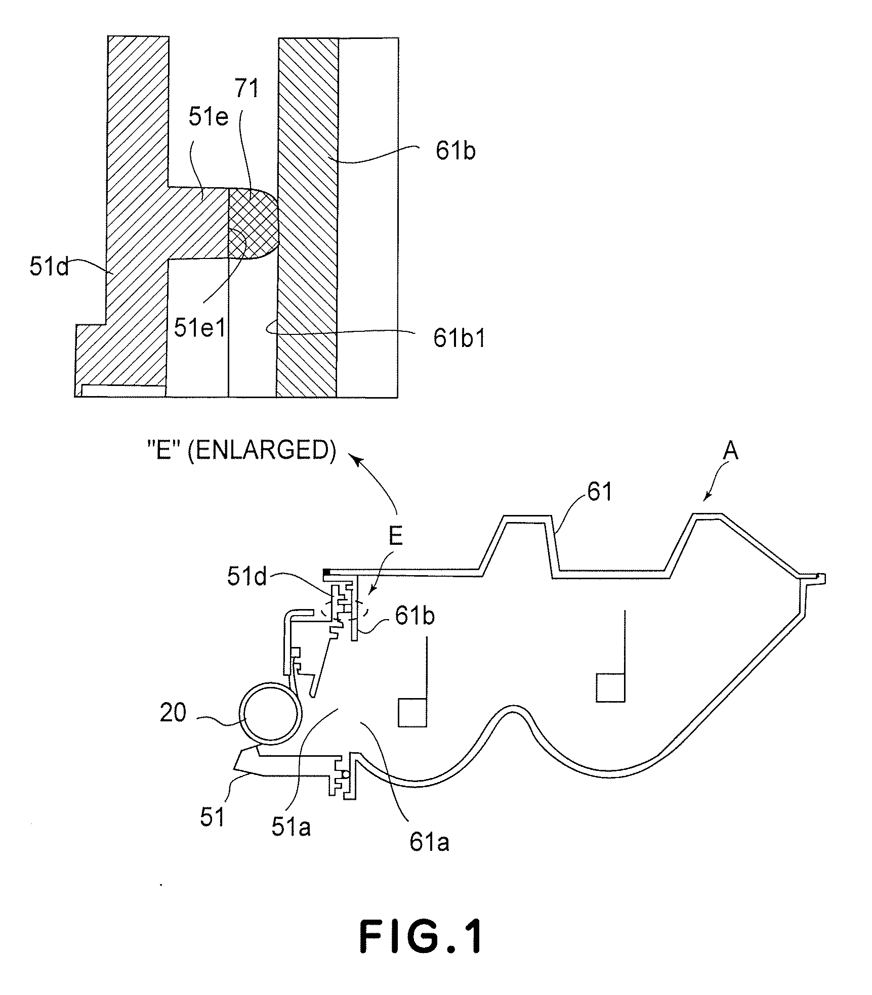
[0120]Referring to FIG. 22, the flange 51d is provided with an elastomer support rib 51e to which liquid elastomer (71) is applied. The elastomer support rib 51e extends in a ma...


PUM


Abstract

A developing apparatus usable with an electrophotographic image forming apparatus for forming an image on a recording material, includes a developer carrying member for developing a latent image formed on an electrophotographic photosensitive member with a developer; a first frame for accommodating the developer, the first frame including a first opening for supplying the developer and a first connecting portion provided around first opening; a second frame containing the developer carrying member, a second opening for receiving supply of the developer from the first opening and a second connecting portion provided around the second opening; an elastomer for connecting the first connecting portion and the second connecting portion with each other with the first opening and the second opening being opposed to each other so as to permit movement of the first frame and the second frame and so as to prevent the developer from leaking between the first connecting portion and the second connecting portion.

Description

FIELD OF THE INVENTION AND RELATED ART[0001]The present invention relates to a developing apparatus, a process cartridge, an electrophotographic image forming apparatus, and a method for assembling developing apparatus.[0002]Here, an electrophotographic image forming apparatus means an apparatus which forms an image on recording medium (for example, recording paper, OHP sheet, etc.) with the use of an electrophotographic image formation process. As examples of an electrophotographic image forming apparatus, an electrophotographic copying machine, an electrophotographic printer (for example, laser printer, LED printer, etc.), a facsimile machine, a wordprocessor, a multifunction printer, etc., may be included.[0003]A process cartridge means a cartridge in which at least a developing means as a processing means, and an electrophotographic photosensitive member, are integrally disposed so that they can be removably mountable in the main assembly of an electrophotographic image forming ...

Claims


Application Information

Patent Timeline
IPC IPC(8): G03G21/18
CPCG03G21/1832G03G15/0898
Inventor MURAKAMI, RYUTAKAWAGUCHI, HIDESHI
Owner CANON KK
Why Eureka
Try Eureka