
Bonding Washer

a washer and washer body technology, applied in the direction of washers, non-insulated conductors, rod connections, etc., can solve the problems of increasing the overall system price, adding material and labor costs, and the cost of grounding lugs themselves

Active Publication Date: 2007-10-25
HUBBELL INC
View PDF36 Cites 83 Cited by
  • Summary
  • Abstract
  • Description
  • Claims
  • Application Information

AI Technical Summary

Benefits of technology

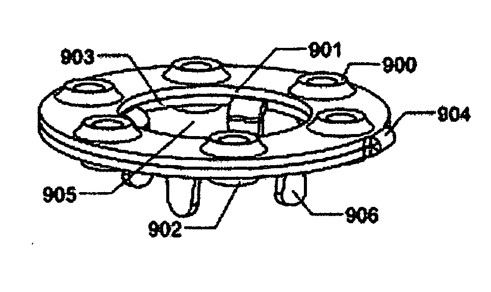
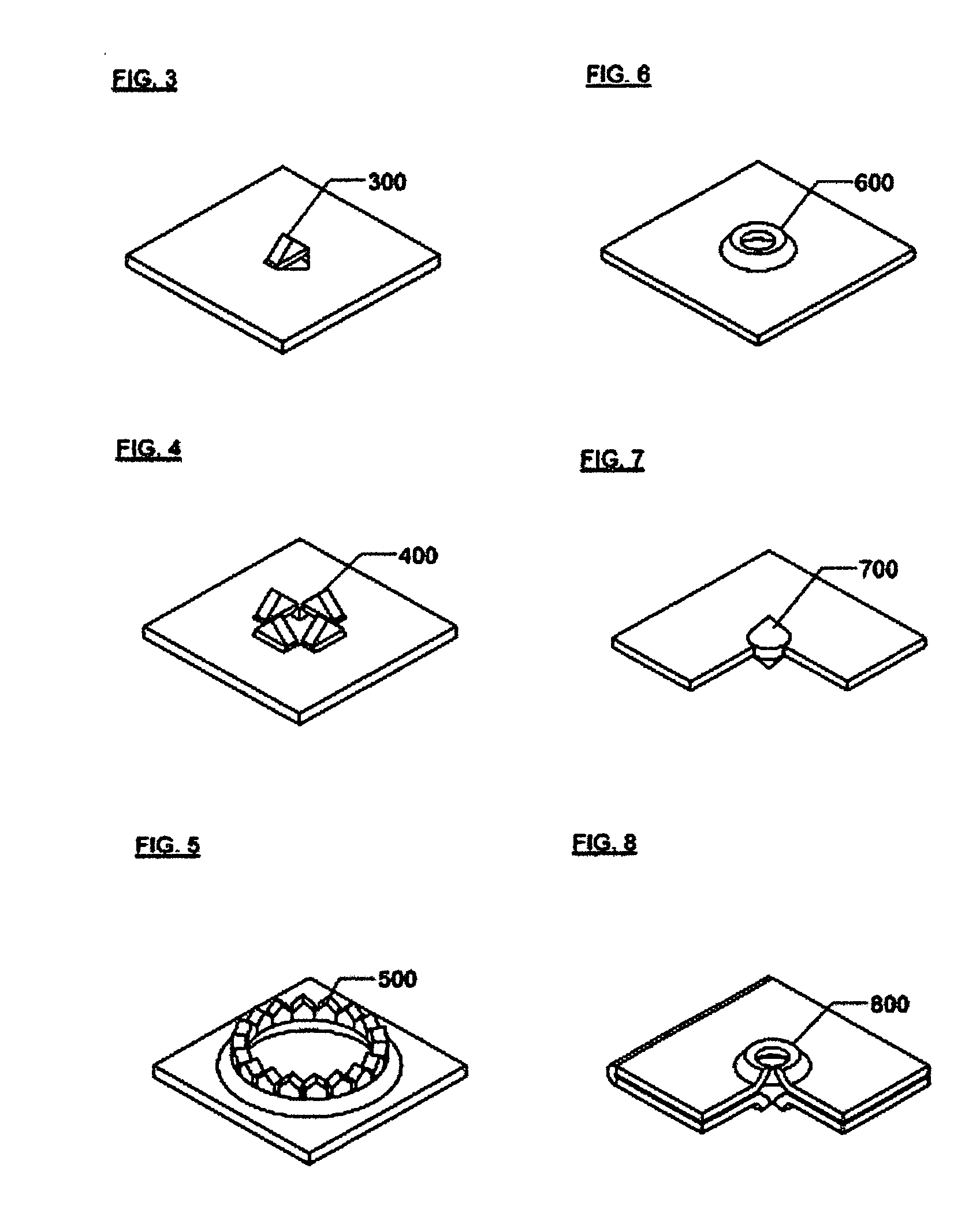
[0029] The present invention consists of a bonding washer for maintaining electrical connection in the joining of two metal pieces, constructed with metal teeth perpendicular to the body of the washer, and shaped so that the washer may be attached to one of the metal pieces before assembly.

Problems solved by technology

The grounding lugs themselves are expensive and time consuming to install and the wiring adds both material and labor cost which increase the price of the overall system.
They will therefore be separated from the nut and bolt by a layer of material and so will not rotate in the usual manner and therefore will be less effective.
In this application, however, depending on the thickness of the anodizing, the star washer may or may not penetrate the anodizing to make connection with the underlying aluminum metal.
One might consider using a washer so thick that the teeth are unable to spring back to the flat condition; however, such a piece would not easily fit in between two metal pieces and may cause the two metal pieces to deform.
Also since a thick washer requires more material, it would be more expensive.
Then, when the washer is tightened against the metal pieces, the teeth will not be able to spring back into the plane of the washer and will be forced to embed themselves into the adjacent piece.
The contact could be made along the inner diameter of a hole in the metal pieces; however, that might limit the amount of contact area available so it would be preferable to contact the metal pieces on an exposed face.
Since the conduction path has four places where current transitions between parts, there is great likelihood of a poor connection at one of the transition points and hence poor reliability.
A final problem is that the screw must generally be made of stainless steel to resist corrosion.
The relatively poor electrical conductivity of stainless steel and the long path through the screw will limit the amount of current which can be safely conducted.
For anodized surfaces the scraping may not be enough to break through the coating.
In the case of application to solar modules, it is necessary to provide for module repair or replacement and a permanent connection is inappropriate.
This is clearly a cumbersome assembly process.
In addition, the grounding stud will be an expensive part to fabricate and since typically four connectors are required per solar module, the total cost will be prohibitive.
Another problem with using available washers is that the washer needs to be inserted in between two metal pieces.
This would clearly be very difficult to do.
There are several problems here.
The first is that the retaining force may not be large enough, and as the large and cumbersome module is positioned, the bolts may be knocked loose.
A second problem is that the available washers are of the star type construction and do not guarantee connection as detailed previously.

Method used


Image

  • Bonding Washer
  • Bonding Washer
  • Bonding Washer

Examples


Embodiment Construction

—FIGS. 1 THROUGH 5-PREFERRED EMBODIMENT

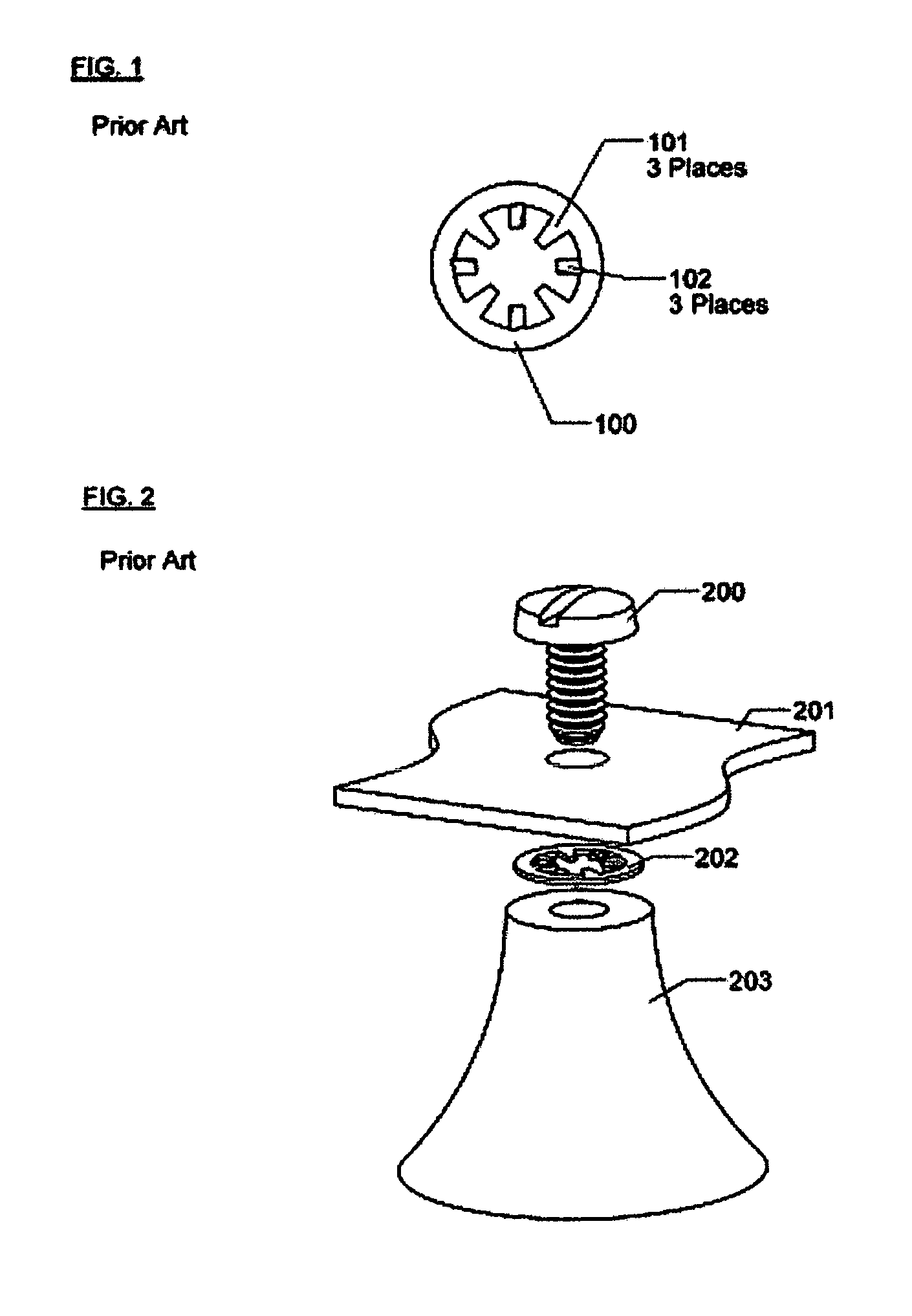
[0142]FIG. 1 illustrates features of the prior art. This star washer is formed from a flat metal piece. Star washer body 100 has two sets of teeth on its internal circumference. FIG. 2 illustrates the prior art in an assembly. The longer teeth 101 will retain the washer on the threads of screw 200, the shorter teeth 102 will make electrical connection to the upper metal piece 201 and lower metal piece 202 when the fastener is tightened. Teeth 102 are twisted out of the plane of the washer body 100. When screw 200 is tightened, upper metal piece 201 and lower metal piece 202 will press on the teeth 102. Since the washer is made out of a spring metal, teeth 102 will resist the tightening. As screw 200 is tightened, teeth 102 will scrape against upper metal piece 200 and lower metal piece 201. This scraping is sufficient to clear dirt or grease from a surface, but is too weak to break through an anodized surface. As screw 200 is further tightened,...


PUM


Abstract

A bonding washer for making electrical connection between two metal pieces that are to be mechanically fastened together. The washer, to be interposed between the two metal pieces, is constructed so as to fasten to one of the pieces before the two pieces are joined. Teeth on the washer, positioned at right angles to the plane of the washer, are forced into each of the two metal pieces when the fastener is tightened, making electrical connection between the two metal pieces.

Description

CROSS-REFERENCE TO RELATED APPLICATIONS [0001] Not Applicable FEDERALLY SPONSORED RESEARCH [0002] Not Applicable REFERENCE TO SEQUENCE LISTING [0003] Not Applicable BACKGROUND OF THE INVENTION [0004] 1. Field of Invention [0005] This invention relates to construction of photovoltaic arrays and other apparatus requiring electrical connection between metal parts. BACKGROUND OF THE INVENTION [0006] 2. Prior Art [0007] This invention has been devised for use in installing a photovoltaic array composed of a number of photovoltaic modules that are assembled onto a larger mounting structure. The frames of the individual photovoltaic modules and the structural pieces on which the modules mount are generally made out of aluminum. The aluminum is anodized to resist corrosion. As in any source of electrical power, to ensure safety the metal pieces must be bonded together. Bonded is used here in the technical sense to mean permanently joined to form an electrically conductive path that ensures ...

Claims


Application Information

Patent Timeline
Patent Type & Authority Applications(United States)
IPC IPC(8): F16B39/24
CPCF16B7/187F16B19/1054F16B43/00F16B39/24F16B19/1072Y02E10/50H01B5/002H01R4/26
Inventor WILEY, BRIAN THOMASCHAN, PALVIN CHEE LEONG
Owner HUBBELL INC
Learn More