Client device characterization of other client device transmissions and reporting of signal qualities to access point(s)

a client device and transmission technology, applied in the field of wireless communication systems, can solve problems such as data collisions, transmission at power levels that provide too few errors, and energy inefficiency, and achieve the effects of reducing the number of errors, and reducing the efficiency of transmission

Active Publication Date: 2007-10-25
AVAGO TECH INT SALES PTE LTD
View PDF14 Cites 81 Cited by
  • Summary
  • Abstract
  • Description
  • Claims
  • Application Information

AI Technical Summary

Problems solved by technology

However, as is generally understood in the art, wireless transmissions may include some error and still provide an accurate transmission.
Thus, transmitting at power levels that provide too few errors is energy inefficient.
But, transmitting at too high a power may interfere with other access points and / or client devices in the proximate area.
At lower received power levels, this protocol can lead to a hidden terminal problem when two devices, generally spaced far apart, are both trying to communication with a third device in the middle.
While the device in the middle can “hear” the two devices on the periphery, these two devices cannot hear one another—potentially creating data collisions with simultaneous transmissions destined for the middle device.
Additional operational difficulties relate to client devices that operate on the fringe of the coverage area of the access point.
During some operations, the access point and client device may adequately communicate but during other operations the same access point client device may not adequately communicate, resulting in loss of service, multiple retransmissions, and other degradation of service quality for not only the inaccessible client device but for other client devices as well.

Method used


Image

  • Client device characterization of other client device transmissions and reporting of signal qualities to access point(s)
  • Client device characterization of other client device transmissions and reporting of signal qualities to access point(s)
  • Client device characterization of other client device transmissions and reporting of signal qualities to access point(s)

Examples


Embodiment Construction

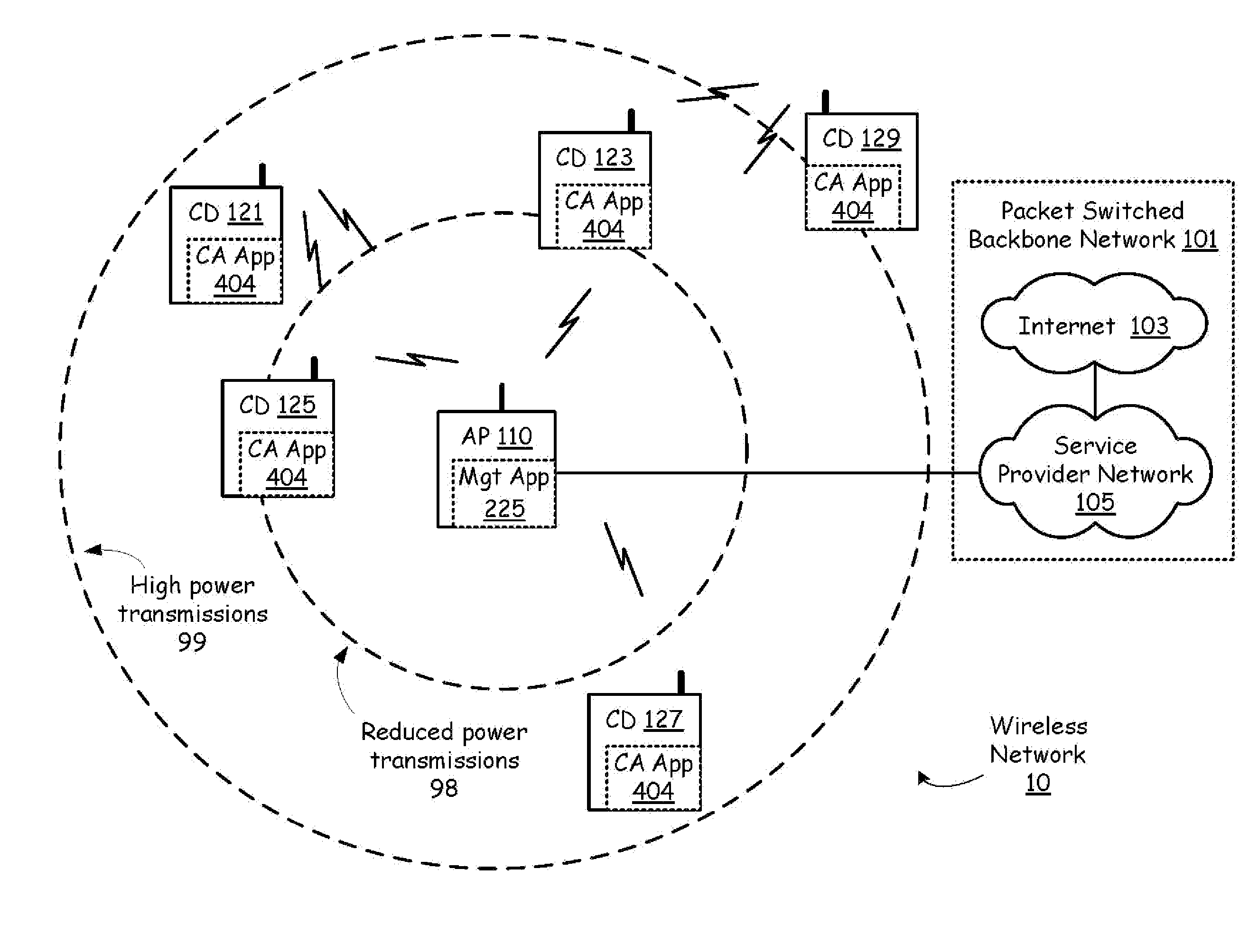
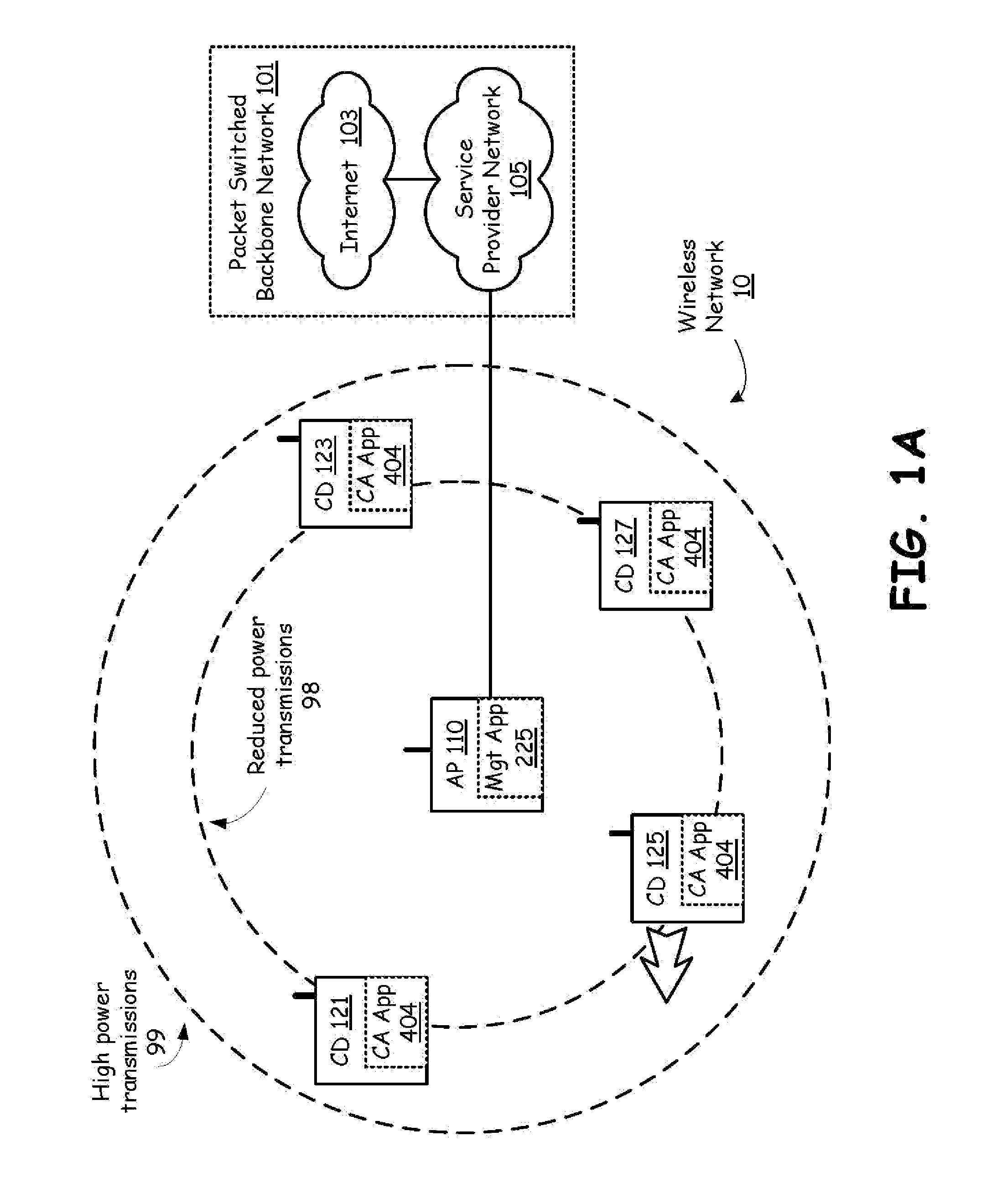
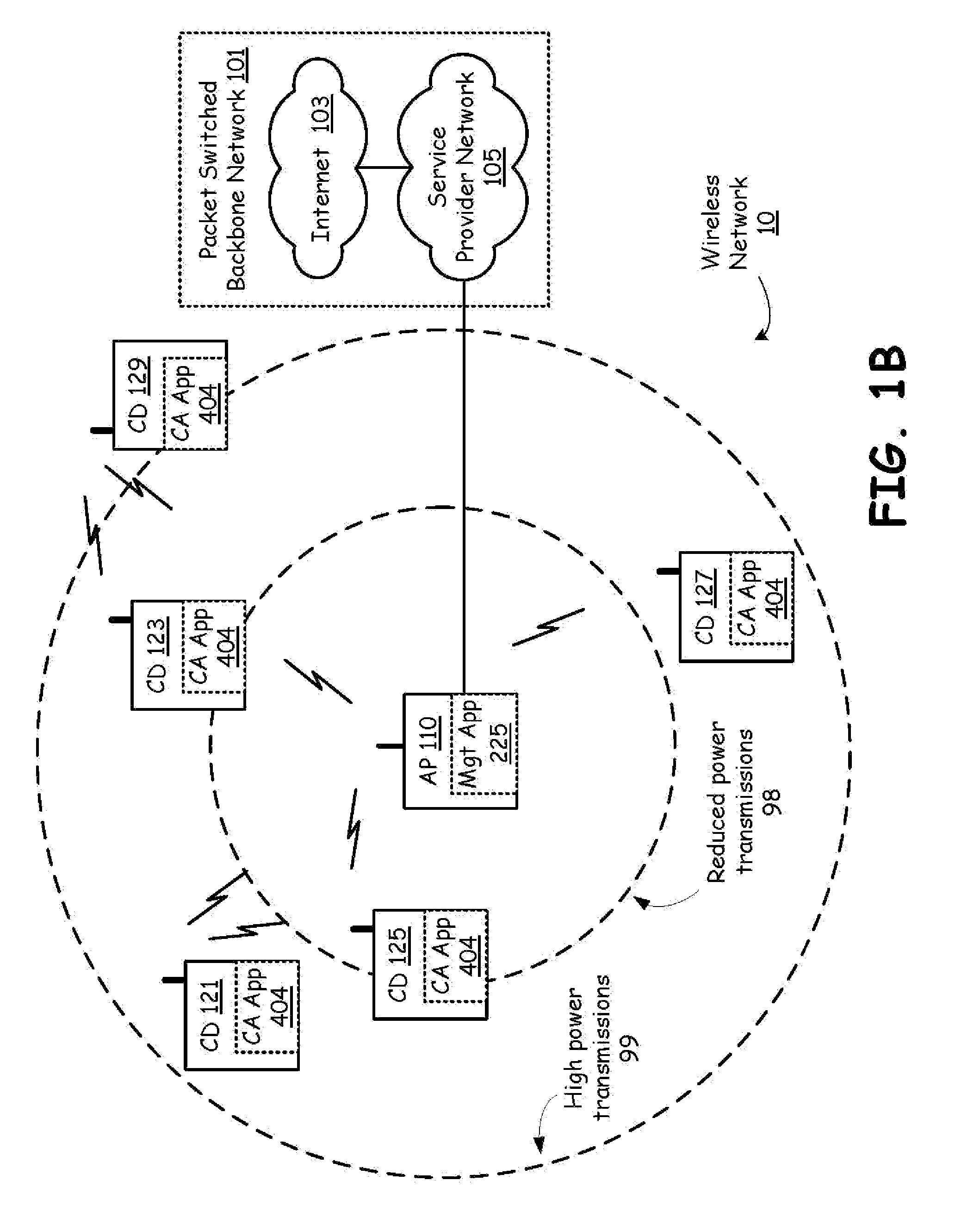
[0047]FIG. 1A is a system diagram illustrating a wireless network in accordance with an embodiment of the present invention, A wireless network 10 includes an access point 110 that is coupled to packet switched backbone network 101. The access point 110 manages communication flow destined for and originating from each of client devices 121, 123, 125 and 127 over a wireless network 10. Via the access point 110, each of the client devices 121, 123, 125 and 127 can access service provider network 105 and Internet 103 to, for example, surf web-sites, download audio and / or video programming, send and receive messages such as text messages, voice message and multimedia messages, access broadcast, stored or streaming audio, video or other multimedia content, play games, send and receive telephone calls, and perform any other activities, provided directly by access point 110 or indirectly through packet switched backbone network 101.

[0048] The access point 110 is capable of transmitting hi...


PUM


Abstract

A wireless network in a communication infrastructure has a packet switched backbone network and includes a plurality of access points and services at least one client device. The access points communicatively couple to the packet switched backbone network and each include access point processing circuitry and access point wireless transceiver circuitry. Each client device has client processing circuitry and client wireless transceiver circuitry. The client devices receive transmissions from other client devices serviced by the plurality of access points and characterize the received transmissions to determine signal qualities of the plurality of transmissions received from the other client devices. The client devices then report the signal qualities of the plurality of transmissions to at least one of the plurality of access points. The access points may forward the signal qualities to other access points, to other client devices, and may alter operation of the wireless network based upon the signal qualities.

Description

CROSS REFERENCES TO RELATED APPLICATIONS [0001] The present application is a continuation-in-part of the following pending patent applications: [0002] 1. U.S. Utility application Ser. No. 11 / 386,583, filed date of Mar. 22, 2006, and entitled: ACCESS POINT AND TERMINAL WIRELESS TRANSMISSION POWER CONTROL BASED ON POINT TO POINT PARAMETER EXCHANGES (Atty. Docket No. BP5279); [0003] 2. U.S. Utility application Ser. No. 11 / 398,930, filed on Apr. 6, 2006, and entitled: ACCESS POINT MULTI-LEVEL TRANSMISSION POWER AND PROTOCOL CONTROL BASED ON THE EXCHANGE OF CHARACTERISTICS (Atty. Docket No. BP5278); and [0004] 3. U.S. Utility application Ser. No. 11 / 429,559, filed on May 5, 2006, and entitled: ACCESS POINT MULTI-LEVEL TRANSMISSION POWER CONTROL SUPPORTING PERIODIC HIGH POWER LEVEL TRANSMISSIONS, (Atty. Docket No. BP5277); [0005] 4. U.S. Utility application Ser. No. 11 / 490,557, filed on Jul. 20, 2006, and entitled: ADAPTIVE COMMUNICATION MANAGEMENT TO ACCOMMODATE HIDDEN TERMINAL CONDITION...

Claims


Application Information

Patent Timeline
Patent Type & Authority Applications(United States)
IPC IPC(8): H04M11/00
CPCH04N21/4126H04W24/00H04W24/08H04W48/08H04W52/04H04W88/02H04B17/382H04W92/20H04B17/24H04B17/309H04B17/318H04B17/336H04W88/08Y02D30/70
Inventor BENNETT, JAMES D.
Owner AVAGO TECH INT SALES PTE LTD
Why Eureka
Try Eureka