Self-contained rotary actuator

a self-contained, rotary actuator technology, applied in the direction of gearings, oblique crank gearings, wobble plate gearings, etc., can solve the problems of cumbersome operator interfaces, low rate of change and diffusion of new technology, relatively high cost, etc., and achieve the effect of drastically reducing the level of custom engineering required for the implementation of a motion control system

Active Publication Date: 2007-10-25
FATHOM5 CORP
View PDF3 Cites 35 Cited by
  • Summary
  • Abstract
  • Description
  • Claims
  • Application Information

AI Technical Summary

Benefits of technology

[0013] As discussed above, automated mechanical systems are generally custom, one-off systems designed essentially from the ground up. The inventor of the standardized rotary actuator module described herein beli

Problems solved by technology

This one-off design methodology tends to result in systems exhibiting relatively high cost and a low rate of change and diffusion of new technology.
Another undesirable effect of custom mechanical design methodology is rapid obsolescence.
In general, operator interfaces are cumbersome, maintenance training is complex, and the logistics trail for maintenance is a permanent and expensive user obligation.
Often, the designer of an automated mechanical system is first faced with the design of a machine joint, which, owing to the relative absence of standardized machine joint solutions, must be performed beginning from basic structural components, such as plates, beams, and bearings.
Although certain components may be designed to interface with the related components, a relatively high degree of engineering effort must still be exerted to ensure that the various components will work together p

Method used


Image

  • Self-contained rotary actuator
  • Self-contained rotary actuator
  • Self-contained rotary actuator

Examples


second embodiment

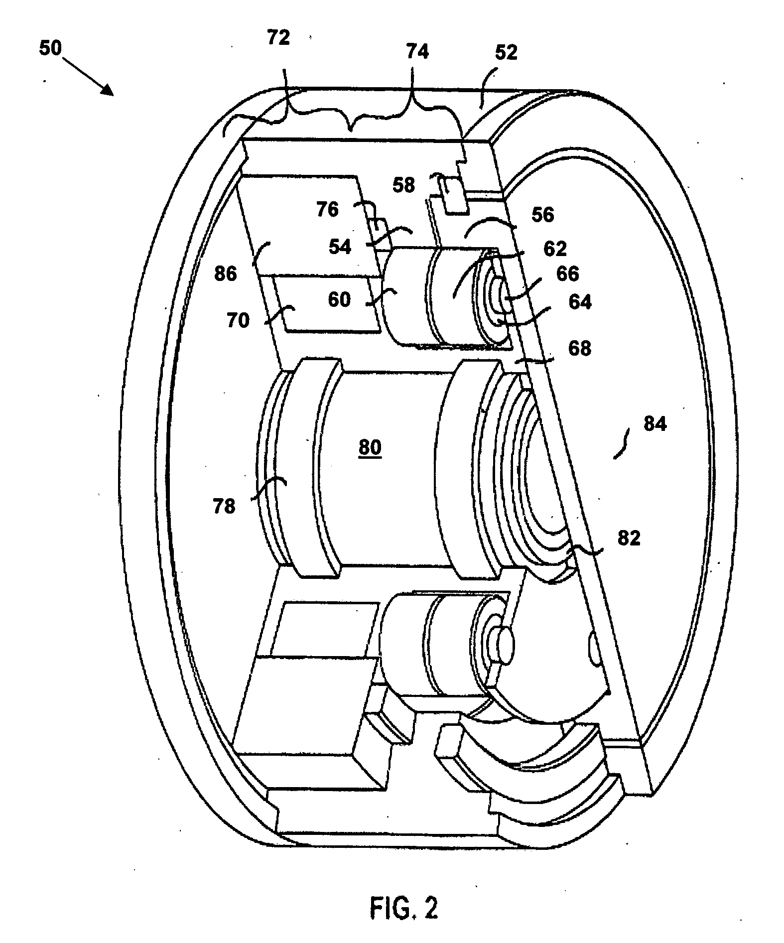
[0050]FIG. 2 depicts rotary actuator 50 in an isometric cutaway view in accordance with the present disclosure. Rotary actuator 50 is typically longer than rotary actuator 10, and there is more concern for the stiffness of the planet cage 68. Accordingly, additional support is provided by bearing 76, embedded in the stiff attachment shell 52 of actuator 50. In order to simplify the design of rotary actuator 50, the planets 60 and 62 are supported by bearings 64 which ride on shafts 66, which are press fit into the planet cage 68 to further increase the stiffness of planet cage 68.

[0051] The output attachment plate 84 and central stationary shaft 230 are mutually supported by bearing 82. Generally, because of higher velocities in the D.C. motor, the structure of the planet cage 68 will be lightened to reduce inertia and the bearings 58, 64, and 76 will be chosen for this higher velocity regime.

[0052] As will be appreciated by those of skill in the art, additional planets tend to inc...

fourth embodiment

[0075]FIG. 4, depicts a cutaway isometric view of a rotary actuator 130 in accordance with the present disclosure. The rotary actuator 130 incorporates a central stationary shaft 156 holding support bearings 155 that support the rotating motor armature 148 that drives the eccentric 157. Support bearings 144 on the eccentric 147 drive the wobble cylinder, which contains the planetary gears 140 and 142 that mesh with the bull gear 134 and sun gear 136 separated by the principal cross-roller bearing or similar large diameter bearing 138.

[0076] Rotary actuator 130 employs a pancake configuration that incorporates an SRM prime mover 150 to produce a high torque / low speed rotary actuator 130.

[0077] Bearing 158 in the output attachment plate 160 supports the end of the stationary shaft 156. Seal 164 separates the output attachment plate 160 from the shell 132 and protects the cross-roller bearing 138 from the elements.

[0078]FIG. 5 depicts a cutaway isometric view of a rotary actuator 170...


PUM


Abstract

A self-contained rotary actuator provides motive power in automated mechanical systems and includes a cross-roller bearing operating as a structural joint. An outer attachment shell rigidly interfaces the automated mechanical system and contains a motor stator and an internal bull gear. The internal bull gear interfaces the cross-roller bearing and provides stiffness and includes internal gear teeth. An output attachment plate mechanism includes an internal ring gear and supports drive shaft bearings. The internal ring gear rigidly interfaces the output attachment plate and includes internal gear teeth. A drive shaft holds a prime mover rotor and an eccentric and associates with the output attachment plate via the drive shaft bearings. A gear train includes a meshing gear having external gear teeth with circular arc surfaces for meshing with the internal gear teeth of the internal bull gear and the internal gear teeth of the internal ring gear and walks a minimal number of the external gear teeth for each rotation of the prime mover rotor. The cross-roller bearing, the outer attachment shell, the drive shaft, and the meshing gear train provide a self-contained, integrated, actuation torque transmitting force from the prime mover along a shortest-possible transmission path.

Description

RELATED APPLICATIONS [0001] This is a continuation-in-part of U.S. patent application Ser. No. 10 / 714,183, filed Nov. 14, 2003, which claims priority of U.S. Provisional Patent Application Ser. No. 60 / 429,276, filed Nov. 25, 2002.FIELD [0002] The present disclosure relates in general to rotary power devices, and specifically to rotary actuators for use in automated machinery. DESCRIPTION OF THE RELATED ART [0003] Most automated mechanical systems developed today are built as unique custom one-off systems employing little or no standardized architecture. This one-off design methodology tends to result in systems exhibiting relatively high cost and a low rate of change and diffusion of new technology. [0004] Another undesirable effect of custom mechanical design methodology is rapid obsolescence. In general, operator interfaces are cumbersome, maintenance training is complex, and the logistics trail for maintenance is a permanent and expensive user obligation. [0005] Often, the design...

Claims


Application Information

Patent Timeline
IPC IPC(8): F16H23/00F16H1/32F16H59/02H02K7/09F16H1/28F16H1/46F16H57/02H02K7/116
CPCB64C13/34F16H1/28F16H1/32Y02E10/725F16H57/021F16H2001/2881H02K7/116F16H1/46Y02E10/72
Inventor TESAR, DELBERT
Owner FATHOM5 CORP
Why Eureka
Try Eureka