Ultrasonic endoscope

Inactive Publication Date: 2007-10-25
FUJI PHOTO OPTICAL CO LTD
View PDF6 Cites 18 Cited by
  • Summary
  • Abstract
  • Description
  • Claims
  • Application Information

AI Technical Summary

Benefits of technology

[0012] The treatment equipment receiving passage is structured by a treatment equipment receiving tube extending to a rear point of the distal hard portion of the insertion portion, i.e., on an angle region side, extending axially of the insertion portion. In the distal hard portion, a treatment equipment receiving passage is formed toward the obliquely forward. The treatment equipment receiving tube and the treatment equipment receiving passage are connected together by a connection pipe. The connection pipe is in a curved form, thus making it possible to change the direction of the treatment equipment in the region of the connection pipe. Accordingly, the treatment equipment, particularly a needle tool having a needle portion at its tip for example, is tend to assume straight when projected out of the treatment equipment lead-out hole. For this reason, the treatment equipment guide member has a guide surface that guides the treatment equipment along the lower surface of a path of the treatment equipment receiving passage directed obliquely upward. The treatment equipment, as moved forward, is directed away from the arrangement region of the ultrasonic transducer.
[0013] As described above, the treatment equipment guide member avoids the distal hard portion of the insertion portion from increasing in length, b

Problems solved by technology

In the event the needle tool goes into contact with the balloon in an inflated state, the balloon results into burst.
However, where the treatment equipment lead-out hole and the ultrasonic transducer are spaced in position, there is a need to increase the region where the needle tool is t

Method used


Image

  • Ultrasonic endoscope
  • Ultrasonic endoscope
  • Ultrasonic endoscope

Examples


Embodiment Construction

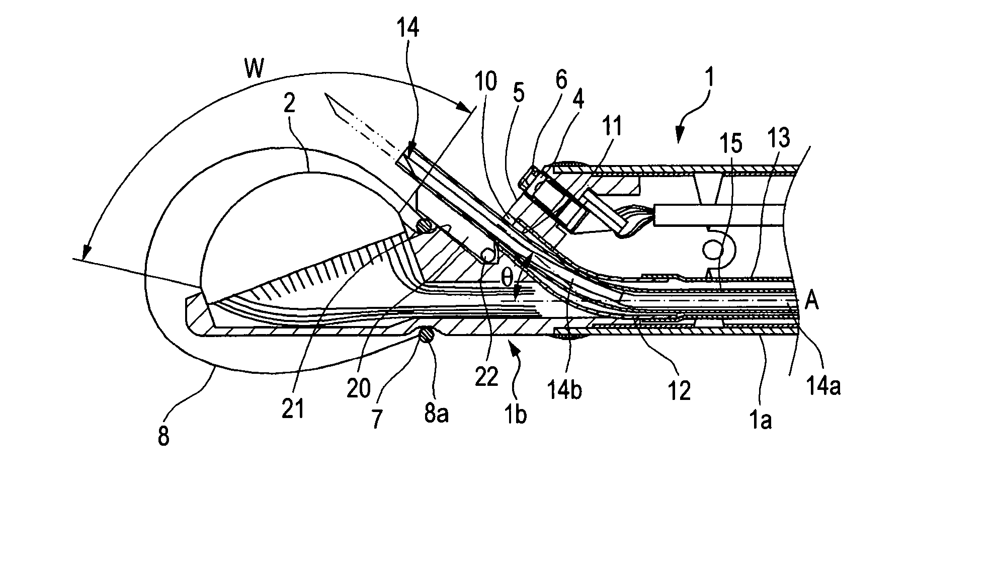
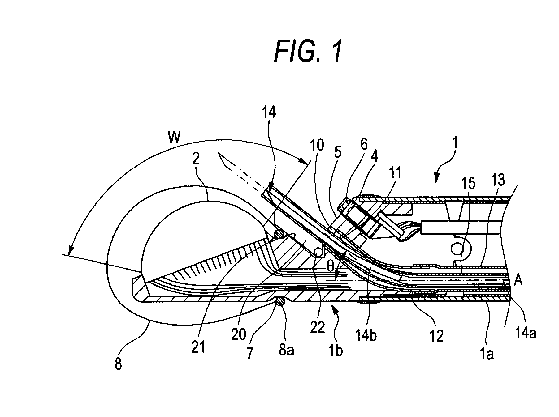
[0018] Based upon the drawings, explanation will now be made on an embodiment according to the present invention. FIG. 1 shows a sectional structure of an ultrasonic endoscope at the distal end portion of its insertion portion while FIG. 2 shows a plan structure of the distal end portion. FIG. 3 is a magnifying view of an essential part of FIG. 1, illustrating a state not passing a needle tool.

[0019] As apparent from the figures, an ultrasonic examining section and an endoscopic viewing section are provided at a distal hard portion 1b provided connected to an angle region 1a of the insertion portion 1. The ultrasonic examining section illustrated is made by an ultrasonic transducer 2 arranged with a multiplicity of ultrasonic vibrators axially of the distal hard portion 1b. The ultrasonic vibrators, constituting the ultrasonic transducer 2, are arranged extending from a point close to the tip of the distal hard portion 1b toward an axially-rear of the distal hard portion 1b and, mo...


PUM


Abstract

An ultrasonic endoscope comprising an insertion portion including a distal hard portion. The insertion portion comprises an ultrasonic transducer arranged in the distal hard portion and a treatment equipment lead-out hole, a slant surface on which an endoscopic viewing section is formed, the slant surface being provided in a position rear of the treatment equipment lead-out hole and a balloon removably arranged in a fit area on the ultrasonic transducer. The distal hard portion comprises a balloon-fit groove between an arrangement region of the ultrasonic transducer and an opening of the treatment equipment lead-out hole. The balloon has an end including a retaining ring that fits in the balloon-fit groove. The distal hard portion further comprises a treatment equipment guide member that slidably guides the treatment equipment across an arrangement area of the balloon-fit groove and up to a position on a beginning side of a scanning range of the ultrasonic transducer.

Description

BACKGROUND OF THE INVENTION [0001] 1. Field of the Invention [0002] The present invention relates to an ultrasonic endoscope arranged with an ultrasonic transducer and an endoscopic viewing section at the distal end of an insertion portion to be inserted in a body cavity, and more particularly to an ultrasonic endoscope adapted to fit a balloon on the ultrasonic transducer. [0003] 2. Description of the Related Art [0004] The ultrasonic endoscope has an insertion portion to be inserted in a body cavity. The insertion portion has a distal hard portion incorporating ultrasonic examining means and endoscopic viewing means therein. The endoscopic viewing means is made up with an illuminating device and a viewing device. The viewing device usually has a solid-state imager. Meanwhile, the ultrasonic examining means is made up by an ultrasonic transducer. The ultrasonic transducer is to transmit an ultrasonic wave toward a body interior and receive a reflection echo from a tissue laminagrap...

Claims


Application Information

Patent Timeline
IPC IPC(8): A61B1/00
CPCA61B1/00082A61B1/00098A61B1/018A61B1/05A61B1/0623A61B8/445A61B8/12A61B8/4281A61B2010/045A61B2019/5276G02B23/2476A61B8/0841A61B2090/378
Inventor KOHNO, SHINICHI
Owner FUJI PHOTO OPTICAL CO LTD
Why Eureka
Try Eureka