Refrigeration Apparatus

a refrigerant and expander technology, applied in the direction of lighting and heating apparatus, liquid fuel engines, machines/engines, etc., can solve the problems of increasing the amount of electric power supplied from the outside, reducing the amount of refrigerant that flows through the expander, etc., to achieve maximum coefficient of performance, reduce the amount of power recoverable, and stable operation

Inactive Publication Date: 2007-11-01
DAIKIN IND LTD
View PDF4 Cites 8 Cited by
  • Summary
  • Abstract
  • Description
  • Claims
  • Application Information

AI Technical Summary

Benefits of technology

[0024] Even when the refrigeration apparatus (10) of the first aspect of the present invention enters a state which creates an imbalance between the amount of refrigerant that flows through the expander (60) and the amount of refrigerant that flows through the compressor (50), the expander (60) and the compressor (50) can be balanced with each other in the amount of passing refrigerant by refrigerant introduction into the expander (60) also from the injection passageway (26). Therefore, the refrigerant conventionally made to bypass the expander (60) will now be allowed to be introduced into the expander (60), and power can be recovered also from the refrigerant from which power cannot conventionally be recovered. Therefore, in accordance with the first aspect of the present invention, it becomes possible to realize the refrigeration apparatus (10) capable of stable operation in a variety of operating conditions without hardly reducing the amount of power recoverable from the refrigerant.
[0025] In the second aspect of the present invention, the controller means (90) adjusts the position of the flow rate control valve (27) so as to provide a maximum coefficient of performance. Therefore, in accordance with the second aspect of the present invention, the expander (60) and the compressor (50) are balanced with each other in the amount of passing refrigerant so that the refrigeration cycle is stably continuously performed and, in addition, the refrigeration cycle can be performed in a condition that accomplishes a maximum coefficient of performance.
[0026] In the fifth aspect of the present invention, the refrigerant circuit (20) includes the bypass passageway (28), thereby making it possible to deliver the outflow of refrigerant from the heat dissipator to the evaporator through both the expander (60) and the bypass passageway (28). Therefore, even when the expander (60) and the compressor (50) cannot be balanced with each other in the amount of passing refrigerant by refrigerant introduction into the expander (60) from the injection passageway (26), it becomes possible to secure an amount of refrigerant that circulates in the refrigerant circuit (20) by causing the refrigerant to flow through the bypass passageway (28). In addition, the controller means (90) of the fifth aspect of the present invention opens the bypass control valve (29) only when the flow rate control valve (27) of the injection passageway (26) is fully opened. As a result of such arrangement, it becomes possible to suppress the refrigerant flow rate in the bypass passageway (28) to the minimum necessary, thereby securing the amount of refrigerant that flows through the expander (60) to the full, and the degree of reduction in the amount of power recoverable from the refrigerant in the expander (60) can be kept to the minimum.

Problems solved by technology

However, the problem with this arrangement is that, if the refrigerant is made to flow into the bypass passageway as described above, the amount of refrigerant that flows through the expander is reduced by an amount corresponding to the amount of refrigerant that flows into the bypass passageway.
This might result in an increase in the amount of electric power to be supplied from the outside for driving the compressor.

Method used


Image

  • Refrigeration Apparatus
  • Refrigeration Apparatus
  • Refrigeration Apparatus

Examples


Embodiment Construction

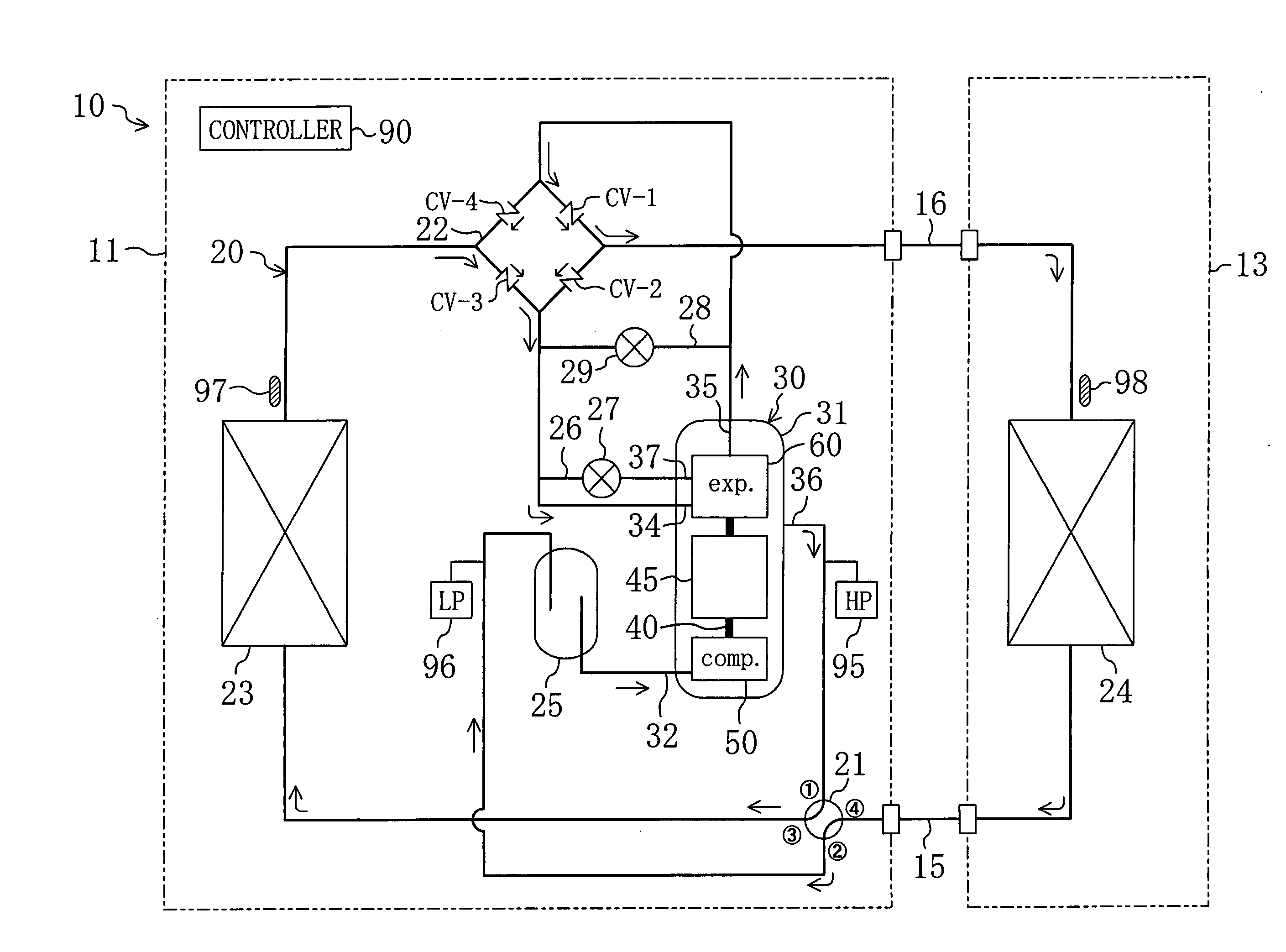
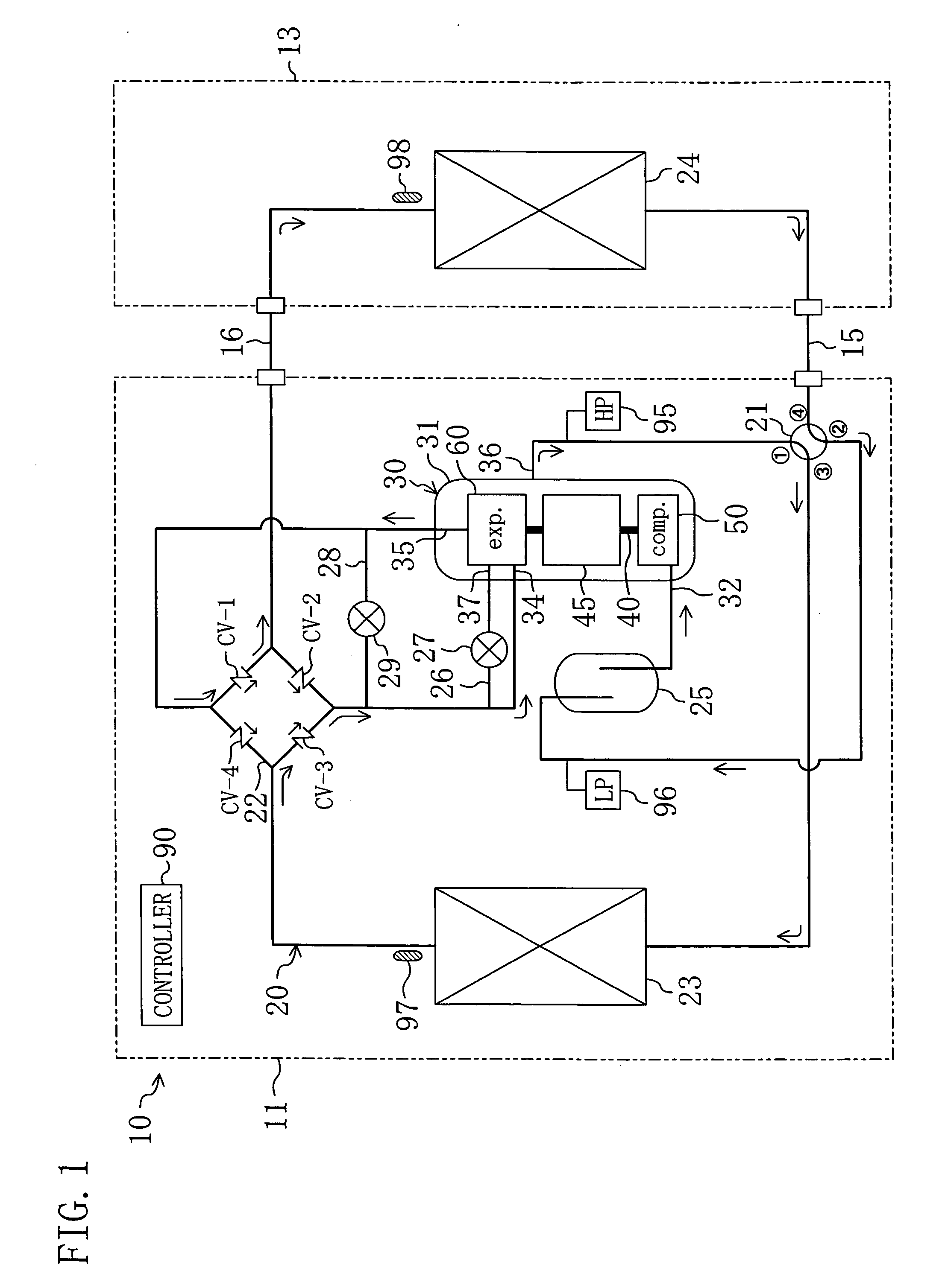
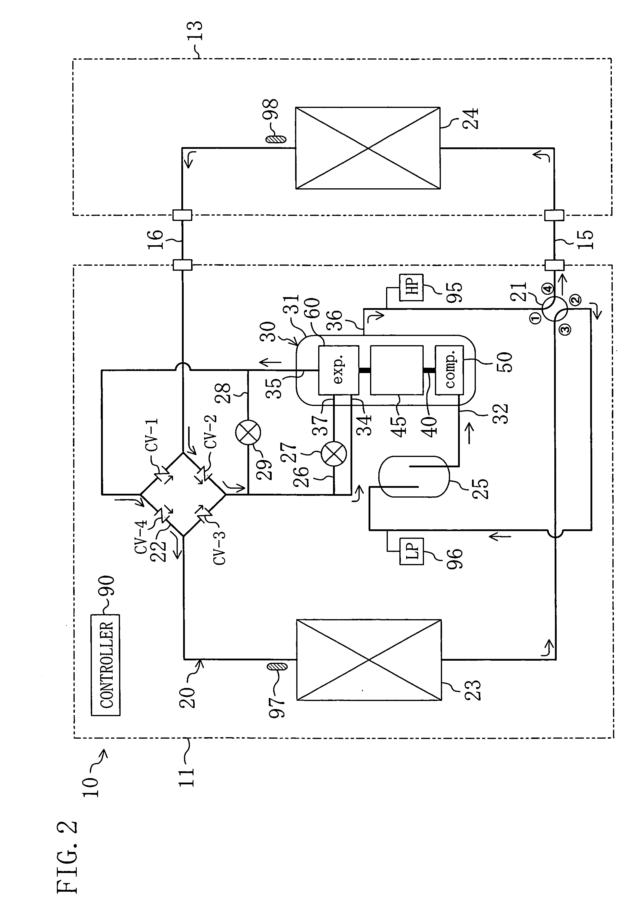
[0048] Hereinafter, an embodiment of the present invention is described in detail with reference to the drawings. An air conditioner (10) of the present embodiment is formed by a refrigeration apparatus of the present invention.

Overall Configuration of the Air Conditioner

[0049] As shown in FIG. 1, the air conditioner (10) is a so-called “separate type” air conditioner, and includes an outdoor unit (11) and an indoor unit (13). The outdoor unit (11) houses therein an outdoor heat exchanger (23), a four way switch valve (21), a bridge circuit (22), an accumulator (25), and a compression / expansion unit (30). The indoor unit (13) houses therein an indoor heat exchanger (24). The outdoor unit (11) is installed outside a building. The indoor unit (13) is installed inside the building. In addition, the outdoor unit (11) and the indoor unit (13) are connected together by a pair of interconnecting pipelines (15, 16). Details about the compression / expansion unit (30) will be described late...


PUM


Abstract

An outdoor heat exchanger (23), an indoor heat exchanger (24), a compression/expansion unit (30), and other circuit components are connected in a refrigerant circuit (20). The compression/expansion unit (30) includes a compression mechanism (50), an electric motor (45), and an expansion mechanism (60). In addition, the refrigerant circuit (20) has an injection pipeline (26). When an injection valve (27) is opened, a portion of high pressure refrigerant after heat dissipation flows into the injection pipeline (26) and is introduced into an expansion chamber (66) of the expansion mechanism (60) in the process of expansion. In the expansion mechanism (60), power is recovered from both high pressure refrigerant introduced into the expansion chamber (66) from an inflow port (34) and high pressure refrigerant introduced into the expansion chamber (66) from the injection pipeline (26).

Description

TECHNICAL FIELD [0001] The present invention relates to a refrigeration apparatus which includes an expander and which performs a refrigeration cycle. BACKGROUND ART [0002] Refrigeration apparatuses operable to perform a refrigeration cycle are well known in the conventional technology. Such a type of refrigeration apparatus has a variety of applications, for example, in the field of air conditioners. Patent Document I discloses a refrigeration apparatus of the type which includes an expander. In the refrigeration apparatus disclosed in Patent Document I, the expander is connected, through a single shaft, to a compressor. In the refrigeration apparatus of Patent Document I, high pressure refrigerant after heat dissipation is expanded in the expander for the recovery of power. The power recovered in the expander is used to drive the compressor, with a view to achieving improvement in the coefficient of performance (COP). [0003] In a typical refrigeration apparatus, refrigerant is cir...

Claims


Application Information

Patent Timeline
Patent Type & Authority Applications(United States)
IPC IPC(8): F25B9/00
CPCF01C11/004F04C18/322F04C18/44F04C23/003F25B2313/0272F25B9/008F25B9/06F25B13/00F25B2309/061F25B1/04F25B1/00F25B1/10F25B11/02
Inventor SAKITANI, KATSUMIMORIWAKI, MICHIOINOKUCHI, YUMESASAKI, YOSHINARI
Owner DAIKIN IND LTD
Why Eureka
Try Eureka