Balancing Shaft for an Internal Combustion Engine and a Method for the Production Thereof

a technology of internal combustion engine and balancing shaft, which is applied in the direction of machines/engines, bearing unit rigid support, couplings, etc., can solve the problems of inadequate construction space and especially small overall construction space required for the hollow body, and achieve the effect of facilitating the positioning of the balancing weight and/or, pushed on with particular ease, and ensuring the reliability of the process

Inactive Publication Date: 2007-11-01
DAIMLER AG
View PDF8 Cites 0 Cited by
  • Summary
  • Abstract
  • Description
  • Claims
  • Application Information

AI Technical Summary

Benefits of technology

[0015] Further, especially preferred embodiment of the method according to the invention. The use of a fluidic internal high pressure for achieving an interference fit further facilitates the positioning of the balancing weight and/or of the functional elements, since the balancing weight and/or the functional elements, with oversize of the hub inside diameter or of the bore diameter, respectively, can be pushed on with particular ease. In addition, the desired interference fit can be set exactly by means of the fluid pressure control of the internal high pressure, since, when producing said interference fit, the wall thicknesses and the material properties of the joining members can be advantageously taken into account with regard to their fracture resistance by a suitable pressure control, so that, during the production of the balancing shaft, the process reliability is absolutely ensured. Furthermore, the joining operation can be effected quickly and with relatively little outlay in terms of equipment.
[0016] In a further, especially preferred embodiment of the method according to the invention, the wall of the through-opening of the hub and/or the wall of the bore with which the balancing weight and/or the functional elements are pushed onto the hollow body are/is designed to be rotationally asymmetric, in which case, by means of fluidic internal high pressure, the hollow body is connected t...

Problems solved by technology

Furthermore, due to the balancing weight being placed locally on the outer circumference, the length of the hollow body is not increased, so that the overall construction...

Method used


Image

  • Balancing Shaft for an Internal Combustion Engine and a Method for the Production Thereof
  • Balancing Shaft for an Internal Combustion Engine and a Method for the Production Thereof

Examples


Embodiment Construction

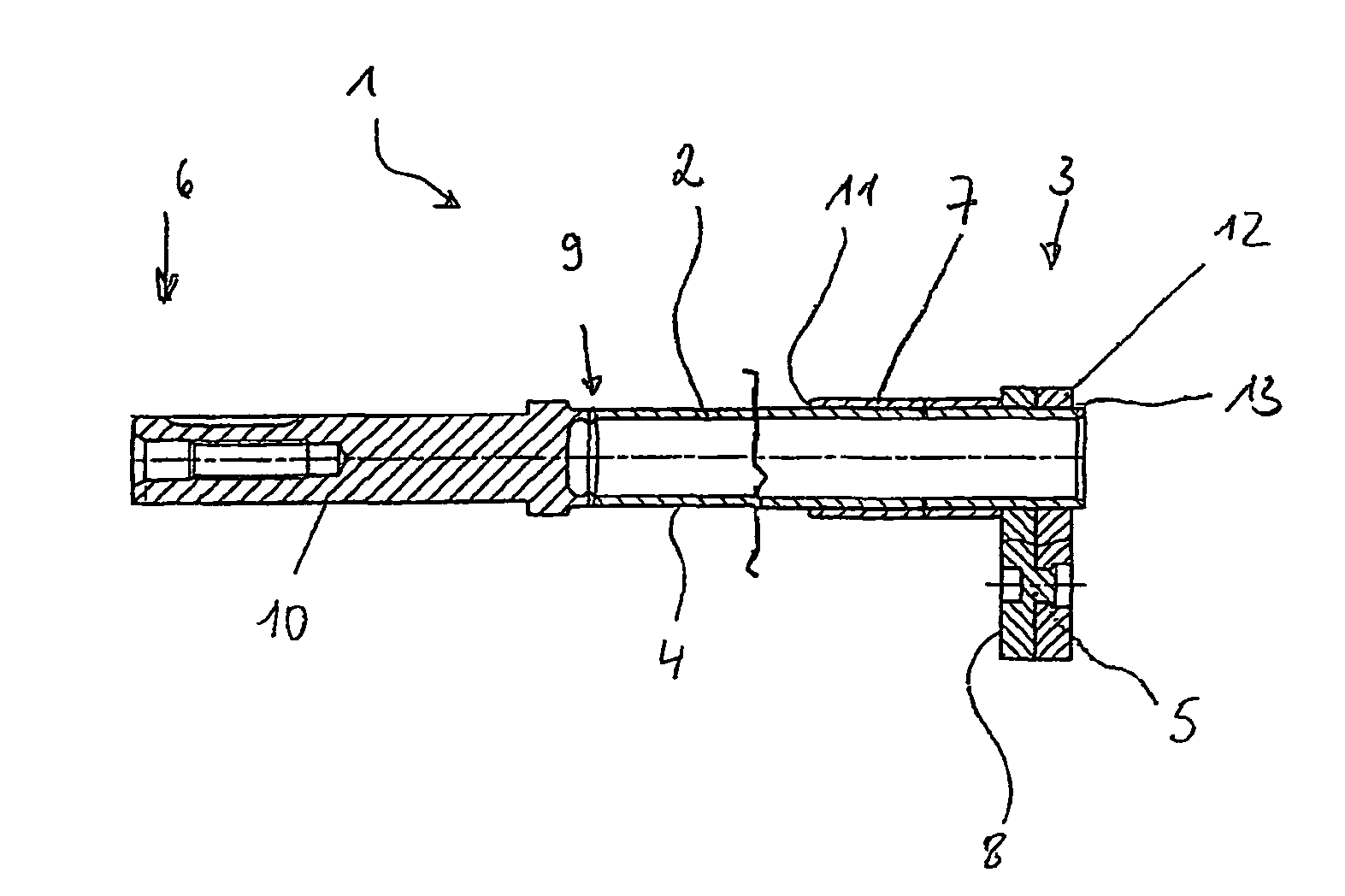
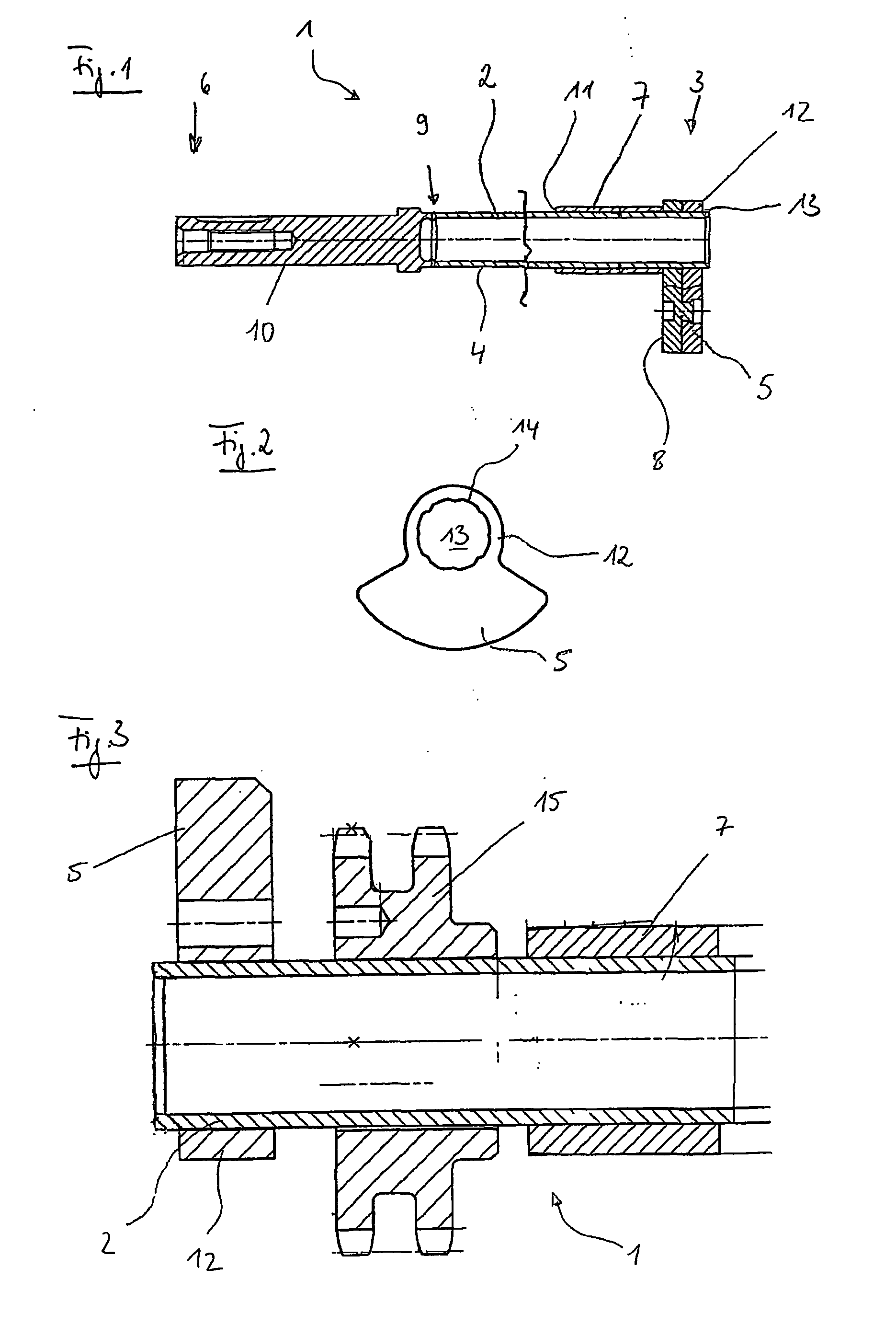
[0022] A balancing shaft 1 for an internal combustion engine is shown in FIG. 1, the shaft 1 consisting of a tubular hollow body 2, which in turn consists of a tubular section of a drawn tube. However, the hollow body 2 may also be produced from a rolled plate which is longitudinally seam-welded at its joint. At one end 3 of the balancing shaft 1, a balancing weight 5 is arranged on the outer circumference 4 of the hollow body 2 and is fastened there. Towards the other end 6 of the balancing shaft 1, the hollow body 2 carries a functional element in the form of a bearing sleeve 7, which is supported at one end on an end face 8 of the balancing weight 5. That end 9 of the hollow body 2 which is remote from the balancing weight is connected in one piece to a connecting component 10.

[0023] The connecting component 10, which is of solid design, forms a continuation of the axial extent of the hollow body 2. The connecting component 10, which may be a turned part, a hot-pressed part, a s...


PUM

PropertyMeasurementUnit
Weightaaaaaaaaaa

Abstract

The invention relates to a balancing shaft for an internal combustion engine and to a method for the production thereof. In this case, the balancing shaft consists of a tubular hollow body and contains a balancing weight and also functional elements arranged on the hollow body. In order-to design a balancing shaft in as simple a manner as possible, which balancing shaft is designed to save construction space and in which the adequate balancing weight is arranged at the suitable location in accordance with the requirements, it is proposed that the balancing weight be arranged on the outer circumference of the hollow body and that it be fastened there.

Description

CROSS REFERENCE TO RELATED APPLICATION [0001] This application is a national stage of PCT / EP2004 / 004541 filed Apr. 29, 2004 and based upon DE 103 20 747.3 filed May 9, 2003 under the International Convention.BACKGROUND OF THE INVENTION [0002] 1. Field of the Invention [0003] The invention relates to a balancing shaft for an internal combustion engine and to a method for the production thereof. [0004] 2. Related Art of the Invention [0005] A balancing shaft of the generic type or a method of the generic type for the production thereof has been disclosed by DE 198 32 987 A1. The balancing shaft described there is of tubular design and has in its interior a balancing weight which extends virtually over its entire length. The tubular part in this case is provided at the circumference with two recesses which each have a centrally situated hole. Passing through each hole is a pin, which in like manner projects through the balancing shaft. The pin serves in this case to fasten the balancin...

Claims


Application Information

Patent Timeline
IPC IPC(8): F16C3/06F16F15/26
CPCF16D1/072F16D1/0858Y10T29/49231F16F2226/04F16F15/268F16C35/00
Inventor HARMS, TORSTENROHWER, FRANK
Owner DAIMLER AG
Why Eureka
Try Eureka