Disk brake

a technology of disc brake and friction pad, which is applied in the direction of brake types, slack adjusters, braking elements, etc., can solve the problems of brake noise or judder, deterioration of the sliding ability of the friction pad relative to the pad spring, and degradation of the function and durability of the pad spring

Active Publication Date: 2007-11-01
HITACHI ASTEMO LTD
View PDF11 Cites 52 Cited by
  • Summary
  • Abstract
  • Description
  • Claims
  • Application Information

AI Technical Summary

Benefits of technology

[0009] The present invention has been made in view of the above-described problems with the conventional techniques. Accordingly, an object of the present invention is to provide a disk brake capable of satisfactorily increasing the strength of pad springs to prevent deformation thereof and to improve the durability and reliability thereof without the need to substantially change the configuration and the like of the pad springs.
[0014] According to the present invention, the reinforcements may include a rectilinear reinforcement rectilinearly provided on the flat plate portion of the connecting plate and oblique reinforcements respectively provided on the two joint portions of the connecting plate to extend obliquely from the opposite ends of the rectilinear reinforcement toward the guide plates.
[0116] Accordingly, the required strength and rigidity can be readily obtained without the need to complicate the equipment, process, etc. for forming the pad springs, for example. Hence, it is possible to minimize the cost increase and to increase productivity. Further, the use of embossing enables a high strength to be obtained without the need to increase the outside dimensions (width and so forth) of the joint portions or to provide bent regions or the like on the joint portions, for example. Accordingly, even when the pad springs are each installed in a narrow gap between the mounting member and the caliper, for example, reinforcement that will not interfere with the surrounding component parts can be formed easily, and the component part shape and the layout components can be designed smoothly.
[0014] According to the present invention, the reinforcements may include a rectilinear reinforcement rectilinearly provided on the flat plate portion of the connecting plate and oblique reinforcements respectively provided on the two joint portions of the connecting plate to extend obliquely from the opposite ends of the rectilinear reinforcement toward the guide plates.
[0014] According to the present invention, the reinforcements may include a rectilinear reinforcement rectilinearly provided on the flat plate portion of the connecting plate and oblique reinforcements respectively provided on the two joint portions of the connecting plate to extend obliquely from the opposite ends of the rectilinear reinforcement toward the guide plates.

Problems solved by technology

This conventional structure, however, involves some problems arising as the slidability of the friction pads relative to the pad springs deteriorates with age.
The elastic deformation of the joints undesirably causes the friction pads to be always pressed toward the disk.
The friction pads thus pressed may drag against the disk, which causes brake noise or judder.
Thus, insufficient strength and rigidity of the joints between the guide plates and the connecting plate lead to degradation of the function and durability of the pad spring.

Method used


Image

  • Disk brake
  • Disk brake
  • Disk brake

Examples


first embodiment

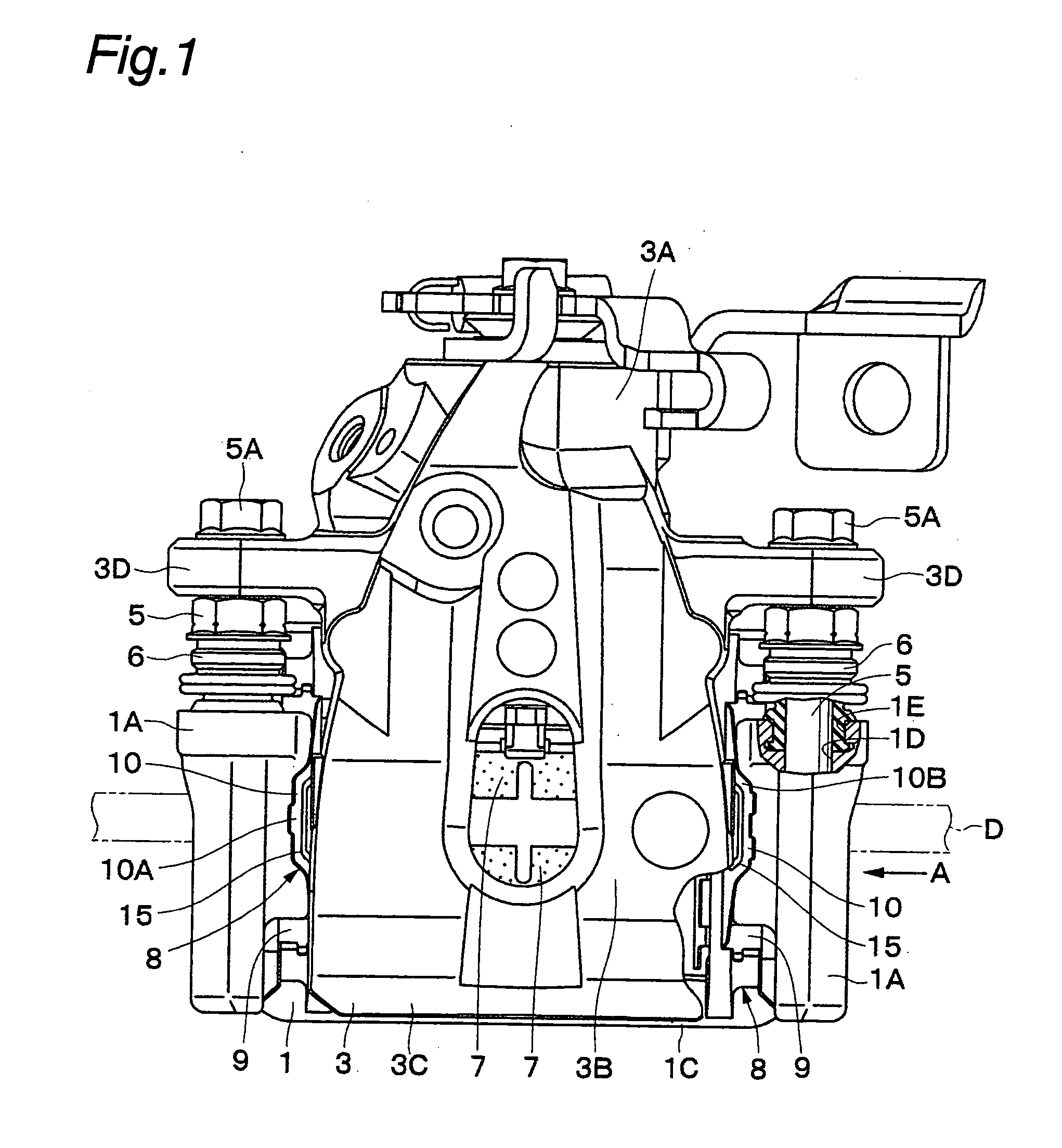
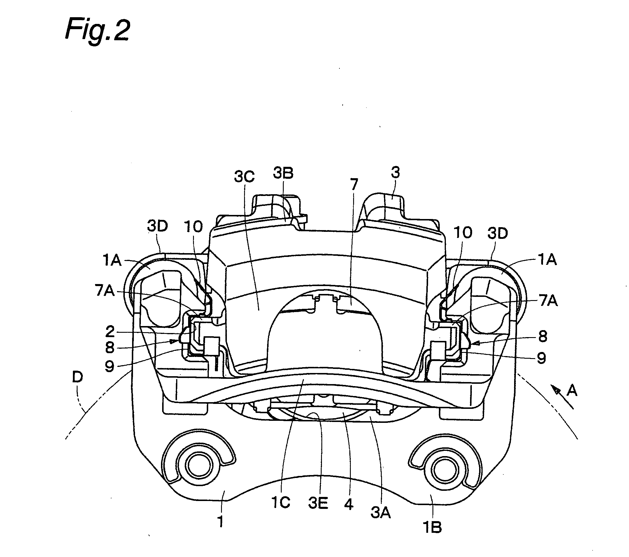
[0033] FIGS. 1 to 8 show the present invention. In this embodiment, a disk brake for use in an automobile will be explained by way of example.

[0034] In the figures, a mounting member 1 is secured to a non-rotating part of a vehicle. As shown in FIGS. 1 and 2, the mounting member 1 is positioned near a disk D that rotates in the direction of the arrow A, together with a wheel (not shown) of the vehicle. In this case, the disk D rotates in the arrow A direction when the vehicle runs in the forward direction.

[0035] The mounting member 1 consists essentially of a pair of arms 1A, 1A, a mounting seat portion 1B, and a bow-shaped reinforcing beam 1C. The arms 1A are spaced apart from each other in the rotational (circumferential) direction of the disk D and extend over the outer periphery of the disk D in the axial direction of the disk D. The mounting seat portion 1B connects together the proximal ends of the arms 1A and is secured to the non-rotating part of the vehicle at the inner si...

fourth embodiment

[0090] FIGS. 11 to 13 show the present invention. The feature of this embodiment resides in that the present invention is applied to a disk brake of the twin-bore specifications.

[0091] A mounting member 41 is secured to a non-rotating part of a vehicle. The mounting member 41 is arranged substantially in the same way as in the first embodiment. That is, the mounting member 41 has a pair of arms 41A, a mounting seat portion 41B, a reinforcing beam 41C, etc. Each arm 41A has U-groove shaped pad guides 42 positioned at the inner and outer sides, respectively, of a disk D.

[0092] A caliper 43 is slidably provided on the mounting member 41 through sliding pins (not shown). The caliper 43 has an inner leg portion (not shown), a bridge portion 43B, an outer leg portion 43C, mounting portions 43D, etc. substantially in the same way as in the first embodiment. The inner leg portion is provided with two (for example) cylinders, and pistons are slidably fitted in the cylinders, respectively.

[...

fifth embodiment

[0097] FIGS. 14 to 16 show the present invention. The feature of this embodiment resides in that the present invention is applied to a disk brake of specifications different from those described above.

[0098] A mounting member 61 is secured to a non-rotating part of a vehicle. The mounting member 61 is arranged substantially in the same way as in the first embodiment. That is, the mounting member 61 has a pair of arms 61A and a mounting seat portion 61B. Each arm 61A has pad guides 62 positioned at the inner and outer sides, respectively, of a disk D. The pad guides 62 are each formed as an L-shaped stepped portion, for example.

[0099] A caliper 63 is slidably provided on the mounting member 61 through sliding pins (not shown). The caliper 63 has an inner leg portion 63A, a bridge portion 63B, an outer leg portion 63C, mounting portions 63D, a cylinder 63E, etc. substantially in the same way as in the first embodiment. The cylinder 63E has a piston 64 slidably fitted therein.

[0100] ...


PUM


Abstract

The strength and rigidity of pad springs are increased with a simple structure to prevent deformation and so forth of the pad springs caused by external force. A mounting member 1 is provided with pad springs 8 for resiliently supporting friction pads 7. Each pad spring 8 has guide plates 9, a connecting plate 10, an engagement plate 11, radially urging portions 12, circumferentially urging portions 13, reinforcement 15, etc. The reinforcement 15 includes a rectilinear reinforcement 15A formed on a flat plate portion 10A of the connecting plate 10 by embossing, for example, and oblique reinforcements 15B formed on joint portions 10B of the connecting plate 10. Thus, the joint portions 10B and so forth of the pad springs 8 can be prevented from being deformed by external force when the brake is activated or during assembling operation, for example, and hence it is possible to prevent positional displacement of the guide plates 9, etc. that would otherwise be caused by the deformation of the joint portions 10B.

Description

BACKGROUND OF THE INVENTION [0001] The present invention relates to a disk brake suitably used to apply braking force to a vehicle, for example, an automobile. [0002] In general, a disk brake provided on a vehicle, e.g. an automobile is arranged as follows. When the driver of the vehicle or the like conducts a braking operation, inner and outer friction pads are pressed against both sides of a disk, thereby applying braking force to the disk (for example, see Japanese Patent Application Publication No. 2003-222171). [0003] This type of conventional disk brake includes a mounting member secured-to a non-rotating part of a vehicle. The mounting member has a pair of arms spaced apart from each other in the rotational direction of a disk. The pair of arms extend over the outer periphery of the disk in the axial direction of the disk. The arms are provided with pad guides formed, for example, from U-grooves. [0004] A caliper is provided on the arms of the mounting member slidably in the ...

Claims


Application Information

Patent Timeline
Patent Type & Authority Applications(United States)
IPC IPC(8): F16D65/40
CPCF16D65/095F16D65/0977F16D65/0972
Inventor TSURUMI, SATORU
Owner HITACHI ASTEMO LTD
Why Eureka
Try Eureka