
Frame Integrated Bicycle Brake System

Inactive Publication Date: 2007-11-01
LYONS JOHN THOMAS
View PDF6 Cites 17 Cited by
  • Summary
  • Abstract
  • Description
  • Claims
  • Application Information

AI Technical Summary

Benefits of technology

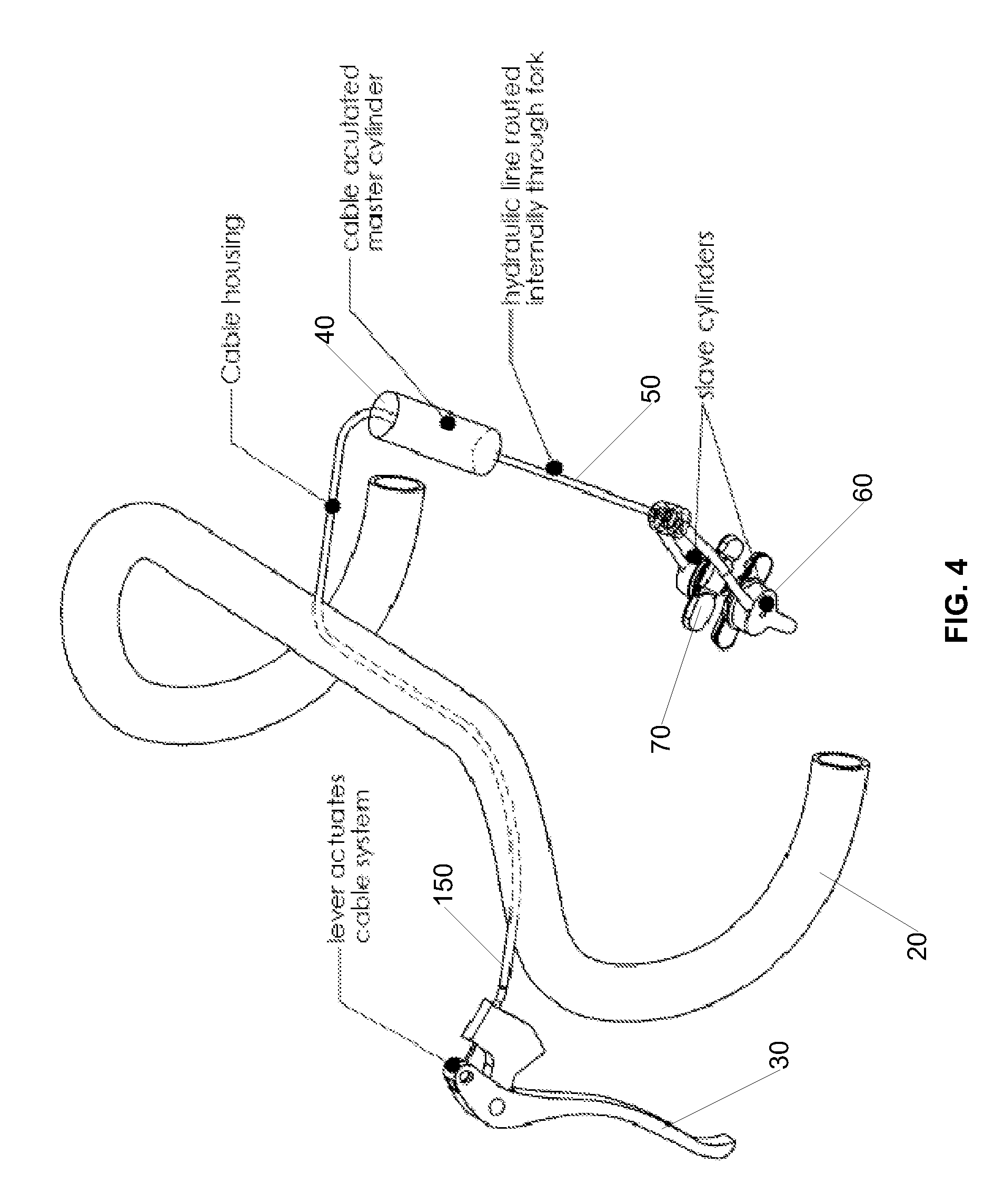
[0008]A portion of a bicycle frame (e.g., fork, seat stay, or chain stay) has a brake assembly housed within it. The brake assembly is an integrated unit inside the portion of the frame that can be operated by a hydraulic mechanism or by a lever and cable assembly or combination of a lever and cable assembly and a hydraulic mechanism. The integration of the brake components into a portion of the bicycle frame eliminates external cable or house routing and also eliminates external attachment points and associated brake components. This provides for a brake system that is both lighter in weight and more aerodynamic than conventional systems. The integrated brake design allows for the control cable or line to be routed through the handle bars and head tube and into the fork (for the front brake) or into the frame (for the rear brake). The stem and handlebar are drilled appropriately to accept internal routing of cable or line. In the case of the current state of the art brake levers, the cable would need to exit the interior of the handlebar to attach to the shift lever.
[0009]The integrated brake design does not require any external cable or line that would reduce the aerodynamic efficiency of the bicycle. As noted above the cable or line could exit the handlebars before attaching to the brake levers, if using the current state of the art. The cable or line routed externally to the handlebars may not reduce the aerodynamic efficiency of the bicycle significantly as it may still be routed under the handle bar tape. Lever designs could be adapted to accept a totally internal routing. Additionally, the integration of the brake into the fork or stay allows for significantly more flexibility in the aerodynamic design of the fork or stay. For example, the shape of the fork body itself will not be constrained by the necessity to have an attachment point for a brake. Because the front fork is one of the first parts of a forward moving bicycle to encounter air resistance it has a significant influence on the airflow around the bicycle. The rear brake (whether mounted to the seat stay or the chain stays of the bicycle) is one of the last portions of a bicycle to pass through a given airspace, and its influence on the size of the aerodynamic wake is significant. The size of this wake is a key contributor to aerodynamic drag (or resistance). The integrated brake design reduces this wake and correspondingly decreases the aerodynamic drag the rider must overcome.

Problems solved by technology

Additionally, because bicycles are typically human powered and humans have limited power output any reduction in weight of the bicycle lessens the burden the rider must overcome when pedaling the bicycle to produce locomotion.
While this is an aerodynamic improvement over previous designs, these conventional brake designs have much room for improvement.
Very often these designs must compromise braking power to improve aerodynamics.
This disrupts the airflow creating a significant wake before the air even has a chance to contact the bicycle frame itself.
The cable or line routed externally to the handlebars may not reduce the aerodynamic efficiency of the bicycle significantly as it may still be routed under the handle bar tape.
The size of this wake is a key contributor to aerodynamic drag (or resistance).

Method used


Image

  • Frame Integrated Bicycle Brake System
  • Frame Integrated Bicycle Brake System
  • Frame Integrated Bicycle Brake System

Examples


Embodiment Construction

[0017]Certain embodiments as disclosed herein provide for an integrated brake assembly that is housed within a portion of the frame of a bicycle and connected to the brake lever through internally routed cables or lines. After reading this description it will become apparent to one skilled in the art how to implement the invention in various alternative embodiments and alternative applications. However, although various embodiments of the present invention will be described herein, it is understood that these embodiments are presented by way of example only, and not limitation. As such, this detailed description of various alternative embodiments should not be construed to limit the scope or breadth of the present invention as set forth in the appended claims.

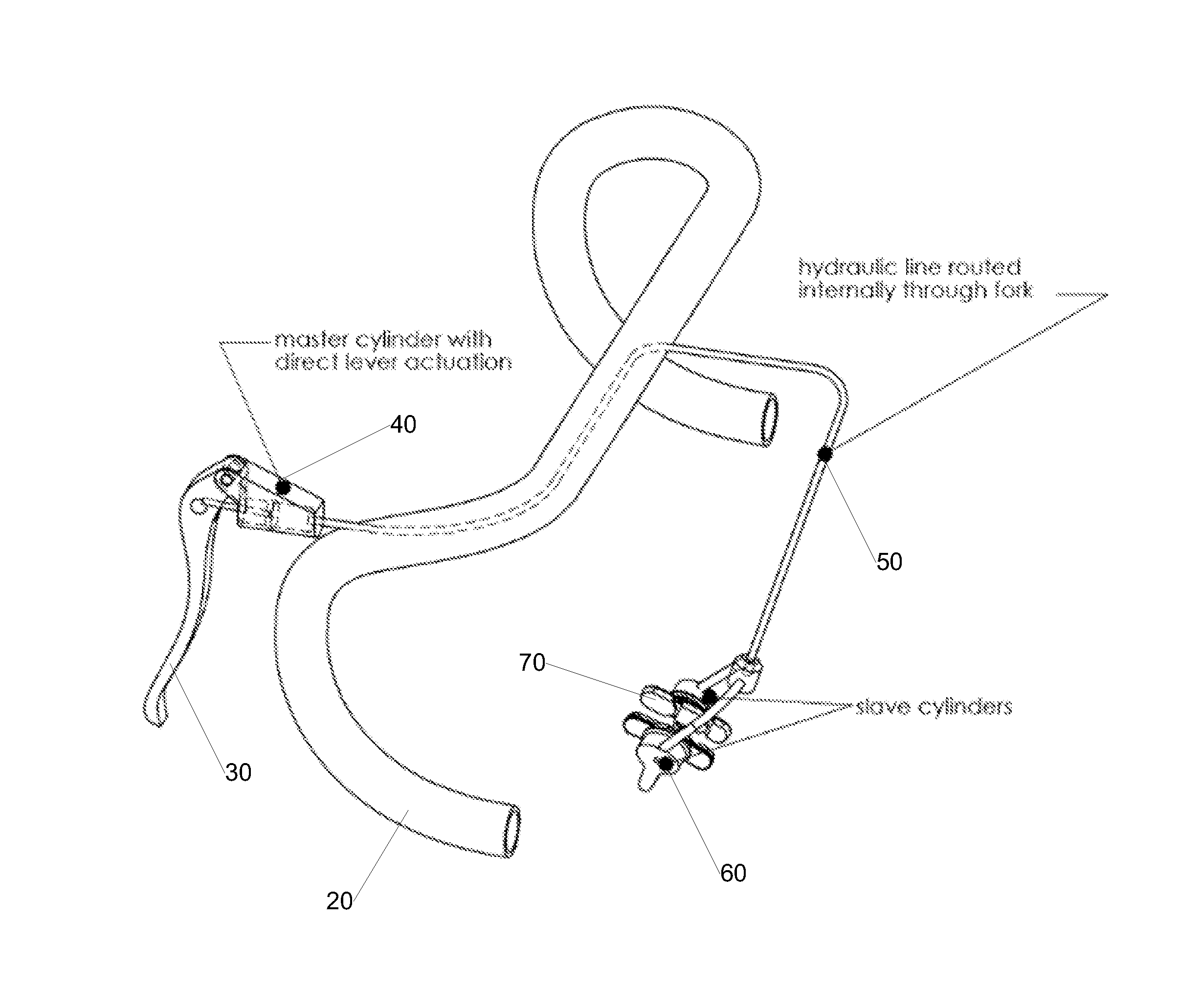
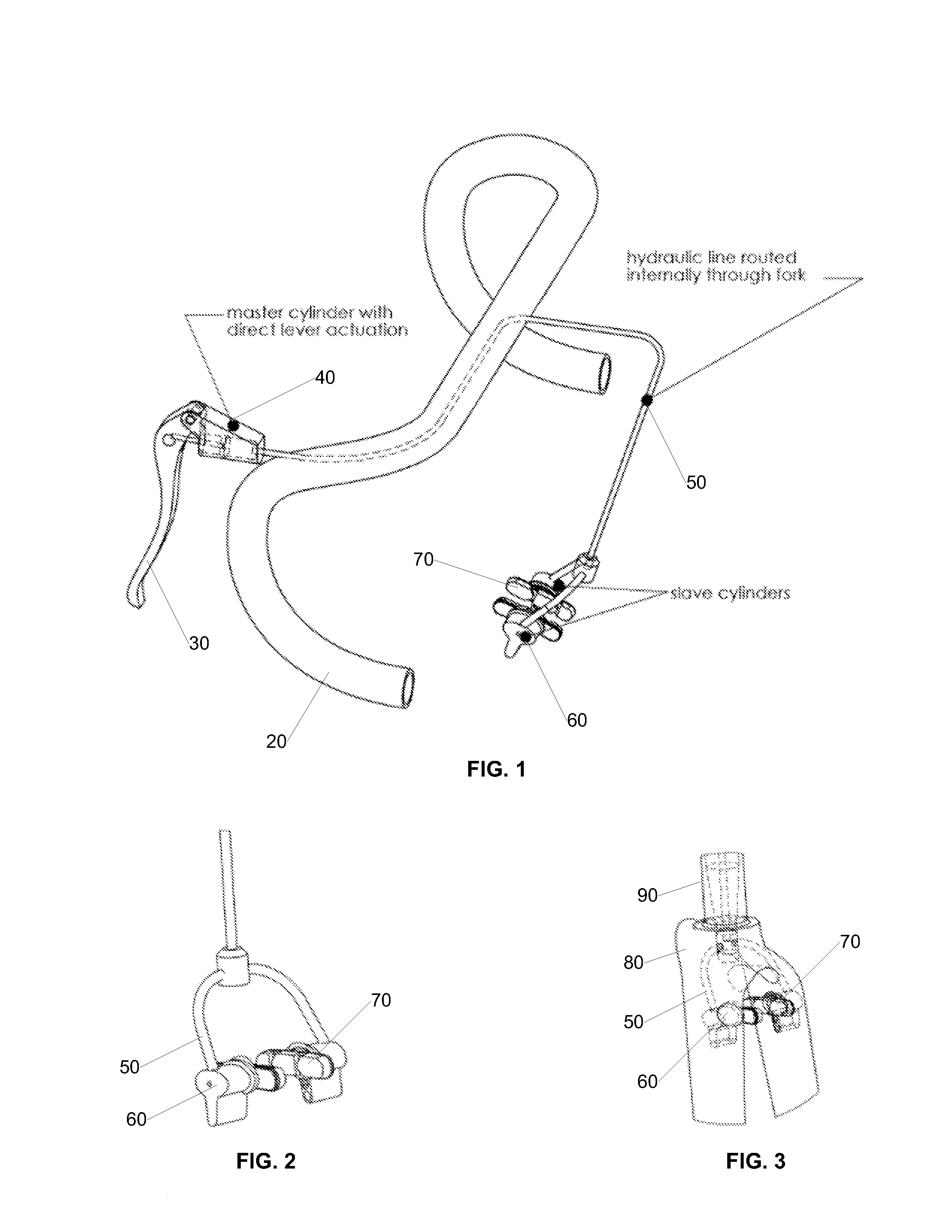
[0018]FIG. 1 is a view diagram illustrating an example frame integrated hydraulic bicycle braking system according to an embodiment of the present invention. In the illustrated embodiment, the braking system comprises a brake l...


PUM


Abstract

A brake system comprises a brake lever that operates an integrated brake assembly that is housed within a portion of the frame of a bicycle. Operation of the brake system can employ a master cylinder that is actuated by the brake lever either directly or by cable. Actuation of the master cylinder causes one or more corresponding slave cylinders to actuate. The slave cylinders are operatively coupled with the master cylinder via a hydraulic line. Actuation of the one or more slave cylinders causes a brake pad that is connected to the slave cylinder to come into contact with the rim of the bicycle.

Description

RELATED APPLICATION[0001]The present application claims priority to co-pending U.S. provisional patent application Ser. No. 60 / 744,834 filed on Apr. 13, 2006 which is incorporated herein by reference in its entirety.BACKGROUND[0002]1. Field of the Invention[0003]The present invention is related to bicycles and braking systems for bicycles.[0004]2. Related Art[0005]Bicycles must have brakes to stop quickly and safely. Conventional bicycle brakes bolt onto frame components such as the fork, seat stay, or chain stay at one or more places. When actuated, the brakes apply a force to the wheel stopping it gradually. The force applied at the brake lever is conveyed through the components of the brake including the cables and levers and attachment points on the frame components. These components and attachment points must be strong enough to transmit this force onto the wheel. Additionally, because bicycles are typically human powered and humans have limited power output any reduction in we...

Claims


Application Information

Patent Timeline
IPC IPC(8): B60T11/00
CPCB60T7/102B62K19/38B60T11/046
Inventor LYONS, JOHN THOMAS
Owner LYONS JOHN THOMAS
Learn More