
Radio frequency identification device support and its manufacturing method

a technology of radio frequency identification and support, which is applied in the direction of mechanical actuation of burglar alarms, instruments, and semiconductor/solid-state device details, etc., can solve the problems of antenna fracture, antenna and chip electrical connection rupture, and material difference between inlay and passport, and achieve good affinity for gluing

Active Publication Date: 2007-11-01
ASK SA (FR)
View PDF14 Cites 27 Cited by
  • Summary
  • Abstract
  • Description
  • Claims
  • Application Information

AI Technical Summary

Benefits of technology

[0008]This is why the purpose of this invention is to counter these drawbacks by offering a radio frequency identification device support that has a good affinity to gluing with paper and that does not delaminate over the thickness and moreover that protects the RFID device from risks of destruction caused by impacts or shocks.

Problems solved by technology

This embodiment has a drawback, as it is not waterproof and particularly cannot resist the passage of the passport through a washing machine.
If the paper on which the antenna is screen-printed is not water resistant, the latter absorbs water and swells up, which causes fractures of the antenna and therefore a rupture of the electrical connection between the antenna and the chip.
One of the drawbacks of such an RFID device is the difference in material between the inlay and the passport.
The latter being made of plastic, the bonding between the two is not optimal.
But the problem of using paper depends on its ability to delaminate over its thickness in case of an attempt of pulling it out.
The delamination can also occur on the edges of the support after a certain period of use, which is a definite disadvantage when the support is intended to be used in a secure document whose lifespan must extend over several years.
Furthermore, a secure document such as a passport implies that the passport pages and consequently the cover supporting the RFID device will be subjected to impacts due to stamping or affixing visas, which exposes the electronic chip to a significant risk of destruction.

Method used


Image

  • Radio frequency identification device support and its manufacturing method
  • Radio frequency identification device support and its manufacturing method
  • Radio frequency identification device support and its manufacturing method

Examples


Embodiment Construction

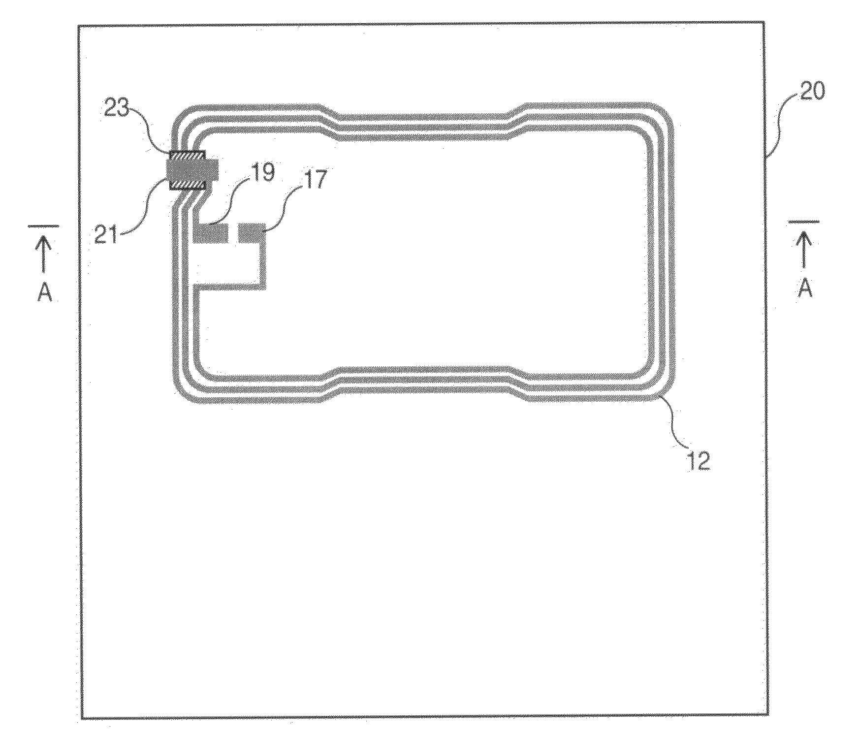
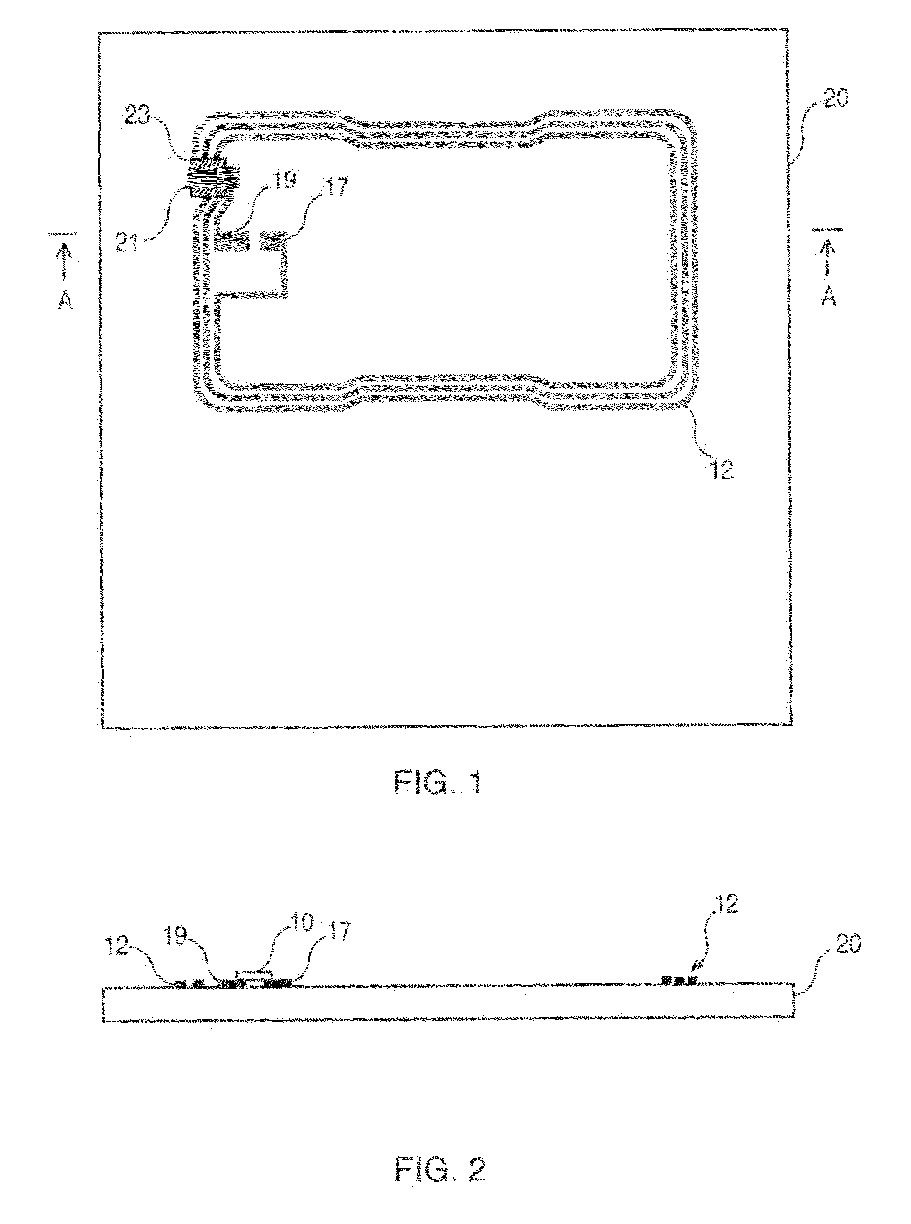
[0030]With reference to FIG. 1, a first layer 20 is used as a support for the antenna and its size corresponds to that of a closed passport, that is to say approximately 88×125 mm. The material of the layer 20 is a material that does not melt and thus does not deform irreversibly when the temperature increases. The material of layer 20 is preferably a material whose cohesion is not modified much during a hot lamination operation which consists in exerting pressure. The antenna 12 that makes up an essential element of the RFID device consists of one or more turns screen printed with an electrically conductive polymer ink, loaded with conductive elements such as silver, copper or carbon. Each end of the antenna is connected to one of the two contacts 17 and 19 of the antenna which are also screen-printed. The turns are interconnected by an electric bridge 21 most commonly referred to as the “cross-over”. An insulating strip 23 of dielectric ink is screen printed between the cross-over...


PUM


Abstract

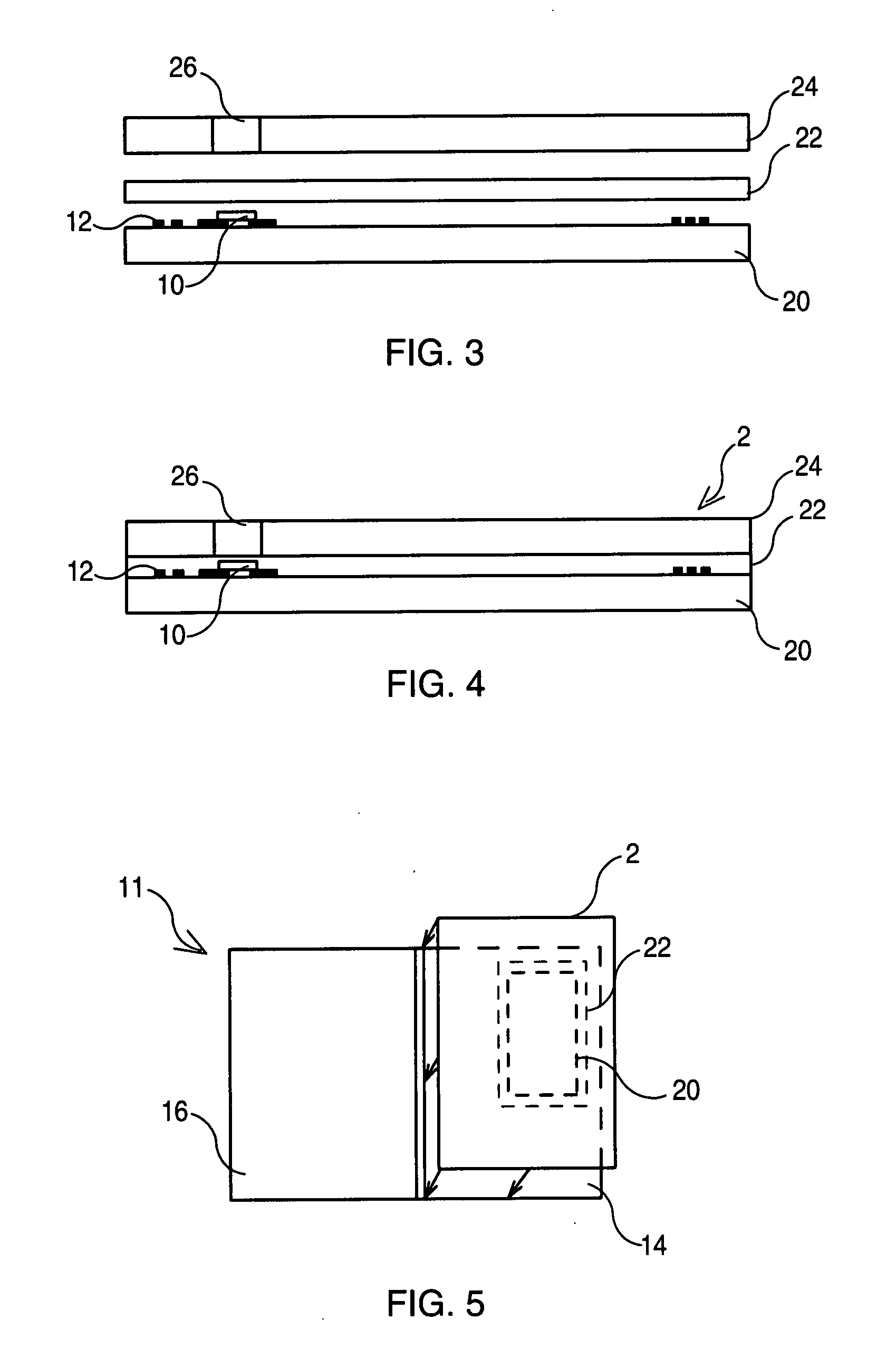
A radio frequency identification device support (2) featuring an antenna (12) screen-printed on a support (20) and a chip (10) connected to the connection terminals (17 and 19) of the antenna. According to a main characteristic of the invention, a thermoplastic layer (22) and a top layer of synthetic paper (24) are laminated on the antenna support (20) so that the antenna and the chip are trapped in the thermoplastic and the three layers (20, 22, and 24) cannot be separated and so that the device is resistant to water and humid environments.

Description

TECHNICAL FIELD[0001]This invention concerns radio frequency identification devices designed to be built into objects such as security documents and specifically concerns a radio frequency identification device support and its manufacturing method.BACKGROUND ART[0002]Contactless Radiofrequency Identification Devices (RFIDs) are increasingly used for identification of persons moving about in controlled access zones or transiting from one zone to another. A contactless RFID is a device made up of an antenna and a chip connected to the terminals of the antenna. The chip is usually not powered and receives its energy by an electromagnetic coupling between the antenna of the reader and the antenna of the RFID, information is exchanged between the RFID and the reader and particularly information stored in the chip that relates to the identification of the holder of the object on which the RFID is located and to his / her authorization to enter into a controlled access zone.[0003]In this man...

Claims


Application Information

Patent Timeline
IPC IPC(8): G08B13/14H01L23/02
CPCG06K19/02G06K19/0775G06K19/07749G06K19/025
Inventor HALOPE, CHRISTOPHELE PAIH, ANNE
Owner ASK SA (FR)
Learn More