Light Formation Apparatus and Control Method of Light Information Apparatus
Inactive Publication Date: 2007-11-01
PANASONIC CORP
View PDF2 Cites 2 Cited by
Summary
Abstract
Description
Claims
Application Information
AI Technical Summary
This helps you quickly interpret patents by identifying the three key elements:
Problems solved by technology
Method used
Benefits of technology
[0060] Since it becomes possible in the present invention not only to respond to dispersion in thickness of a protective layer of an optical recording medium without depending on optical conditions in a design of an optical head, but also to keep outgoing power of an output to a side of an objective lens constant, it becomes possible to achieve an optical information apparatus which can obtain a stable control signal and a stable reproductive signal regardless of the thickness dispersion of the protective layer of the optical recording medium.
Problems solved by technology
However, spherical aberration resulting from an error of thickness of a protective layer protecting a recording layer of an optical recording medium is proportional to the biquadrate of NA.
At this time, while reproducing the optical recording medium 10, power more than needed is irradiated on the optical recording medium 10, and there is a possibility of accidentally degrading recorded information recorded on the optical recording medium 10.
At this time, while reproducing the optical recording medium 10, reproductive signal quality deteriorates, and there is a possibility that it may become impossible to reproduce recording information.
Nevertheless, the
Method used
Image
Click on the blue label to locate the original text in one second.
Reading with bidirectional positioning of images and text.
Examples
embodiment 1
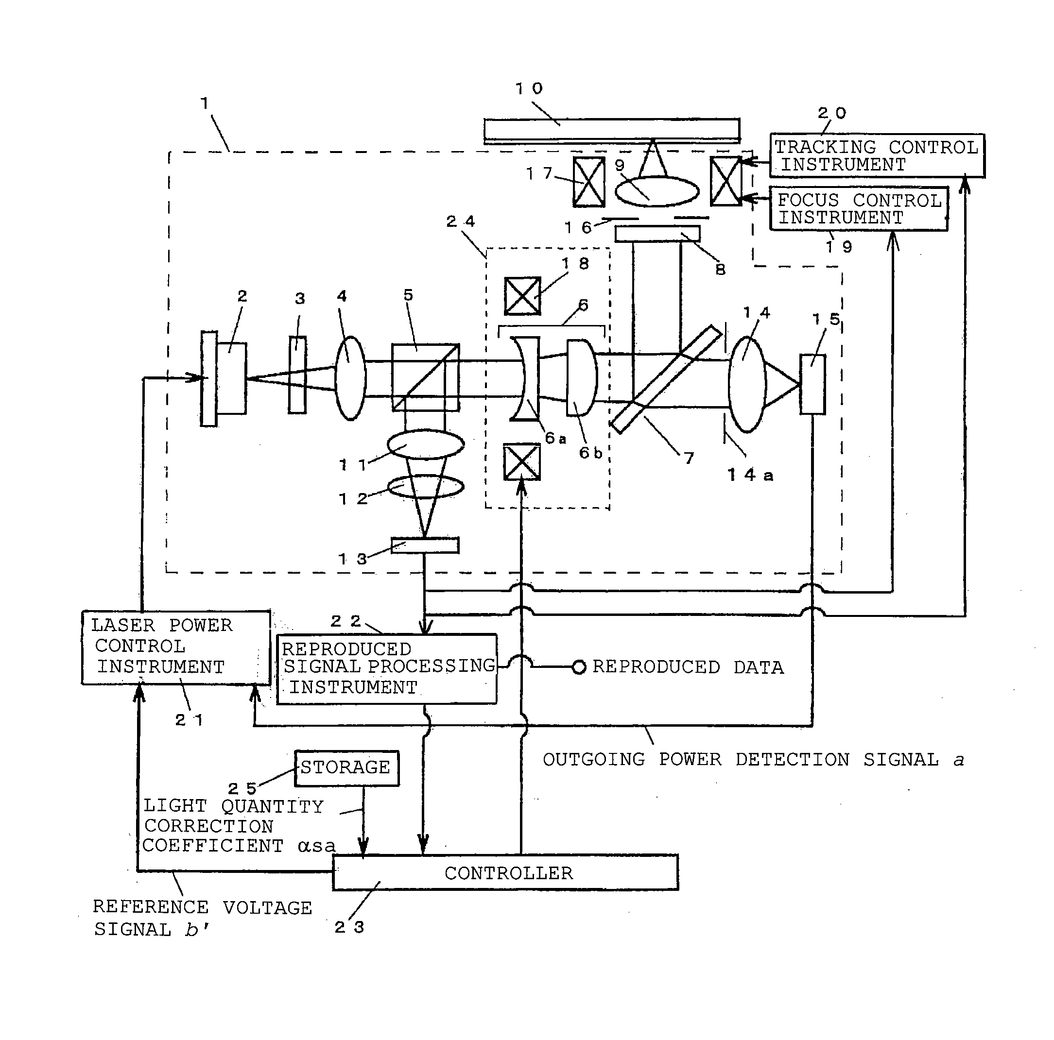
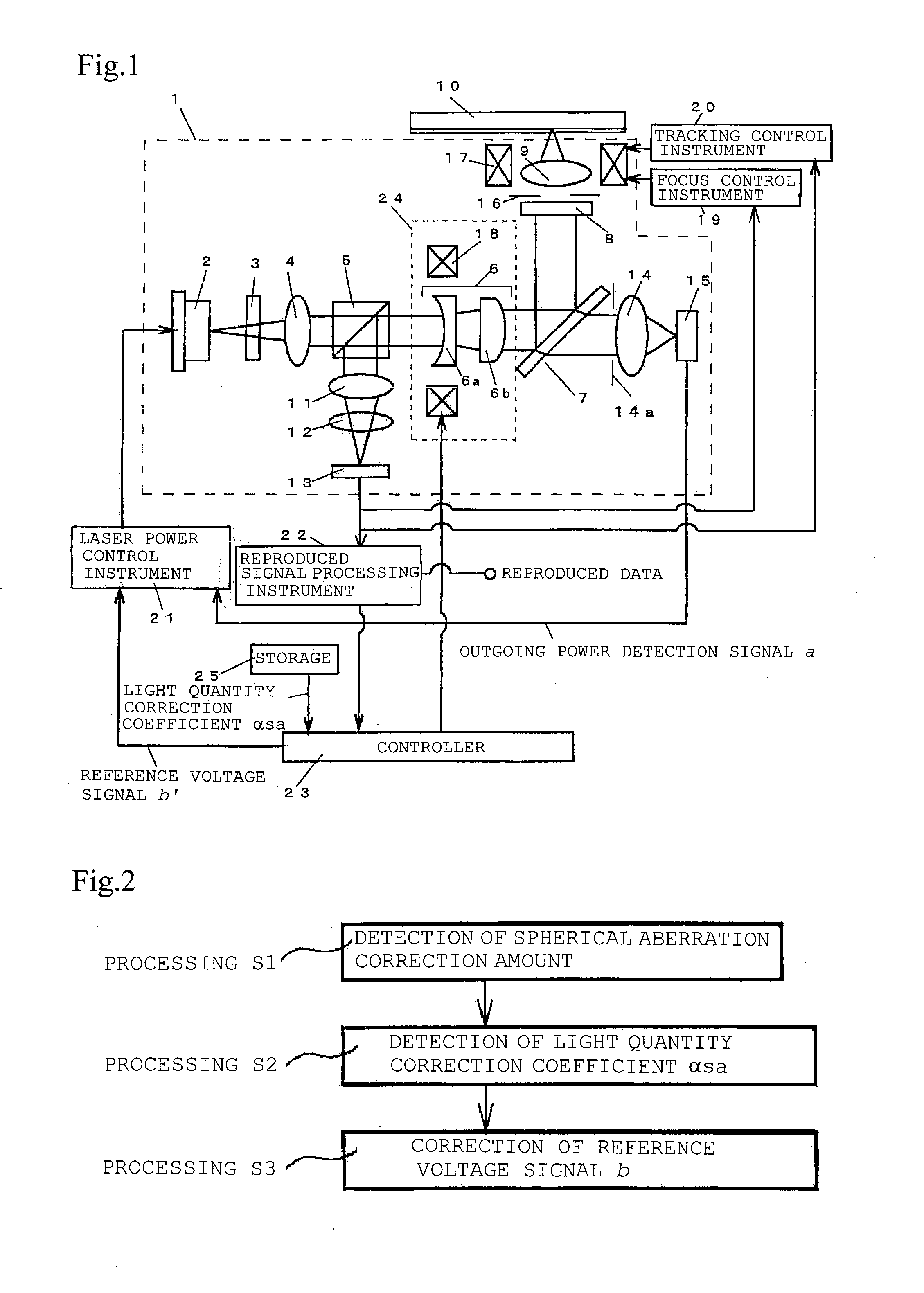
[0120]FIG. 1 is a schematic diagram of an optical information apparatus in a first embodiment. In FIG. 1, the same reference numerals are used for the same constituents as those in FIG. 13, and their detailed description is omitted.
[0121] In FIG. 1, reference numeral 14 denotes a lens which condenses light, permeating the mirror 7, to the light quantity detector 15, reference numeral 15 denotes the light quantity detector which transforms a received light beam into an electric signal, and light quantity detection instrument is constituted of the lens 14 and light quantity detector 15. In addition, reference numeral 22 denotes reproduced signal processing instrument, reference numeral 23 denotes a controller, and reference numeral 25 denotes storage.
[0122] A light beam received by the photodetector 13 is transformed into an electric signal, which is supplied to the focus control instrument 19, tracking control instrument 20, and reproductive signal processing instrument 22.
[0123] ...
embodiment 2
[0155]FIG. 8 is a schematic diagram showing structure of an optical information apparatus in a second embodiment. In FIG. 7, the same reference numerals are used for the same constituents as those in FIG. 1 or 13, and their detailed description is omitted. In addition, in FIG. 8, reference numeral 40 denotes an optical recording medium having two layers of recording layers, reference numeral 48 denotes focus control instrument, reference numeral 49 denotes tracking control instrument, and reference numeral 53 denotes a controller.
[0156]FIG. 9 shows an example of a schematic diagram of an optical recording medium having two layers of recording layers. It has constitution of a surface 87, a protective layer 82, a first recording layer 83, an interlayer 85, a second recording layer 84, and a base material 86, which is a back, from an optical head side in order. The protective layer 82 and interlayers 85 are transparent media such as a resin. Since the interlayer 85 is between the firs...
PUM
Abstract
When a spherical aberration generated on an optical recording medium is optically corrected, there has been a problem of irradiation power change of an output on an objective lens side due to a change of a signal level detected by a light quantity detector in response to the correction value. An optical information device is provided with a laser (2) for projecting optical beams; an objective lens (9) and the like for focusing the optical beams projected from the laser (2) on an optical recording medium (10); a spherical aberration correcting means (24), which is arranged on an optical axis of the optical beams connecting the laser (2) and the objective lens (9) and corrects a spherical aberration generated on the optical recording medium (10); a polarization beam splitter (5) for splitting the optical beams projected from the laser (2) into a plurality of beams; a light quantity detector (15) which receives one of the optical beams split by the polarization beam splitter (5) and outputs an electric signal corresponding to the receiving light quantity; a laser power control means (21), which controls the projection power of the laser beam source based on the electric signal from the light quantity detector (15); and a controller (23), which performs correction, such as to change the projection power of the laser (2) in response to a correction quantity of the spherical aberration correcting means (24).
Description
[0001] This application is a U.S. national phase application of PCT International Application PCT / JP2005 / 011296, filed Jun. 20, 2005. TECHNICAL FIELD [0002] The present invention relates to an optical information apparatus which performs write-in and read-out of an information signal to an optical recording medium like an optical disk, a magneto-optical disk, or an optical card, its control method, and the like. BACKGROUND ART [0003] Optical memory technology using an optical recording medium having a pit-like pattern as a high-density and large-capacity memory medium has been practically used while having extended applications such as a digital [0004] In recent years, in order to further highly densify recording density of an optical recording medium, it has been investigated to enlarge numerical aperture (NA) of an objective lens which converges a light beam on an optical recording medium to form a diffraction-limited minute spot. However, spherical aberration resulting from an er...
Claims
Application Information
Patent Timeline
Application Date:The date an application was filed.
Publication Date:The date a patent or application was officially published.
First Publication Date:The earliest publication date of a patent with the same application number.
Issue Date:Publication date of the patent grant document.
PCT Entry Date:The Entry date of PCT National Phase.
Estimated Expiry Date:The statutory expiry date of a patent right according to the Patent Law, and it is the longest term of protection that the patent right can achieve without the termination of the patent right due to other reasons(Term extension factor has been taken into account ).
Invalid Date:Actual expiry date is based on effective date or publication date of legal transaction data of invalid patent.