Multi-channel optical pickup and optical recording/reproducing apparatus employing the same

Inactive Publication Date: 2009-07-09
SAMSUNG ELECTRONICS CO LTD
View PDF10 Cites 0 Cited by
  • Summary
  • Abstract
  • Description
  • Claims
  • Application Information

AI Technical Summary

Benefits of technology

[0009]Aspects of the present invention provide a multi-channel optical pick-up that provides spots on an information storage medium to stably record and / or reproduce signals by preventing defocus of the spots with respect to a center spot, and a multi-channel optical recording and / or reproducing apparatus employing the same.
[0010]According to an aspect of the present invention, there is provided a multi-channel optical pick-up to focus a plurality of light beams on an information storage medium, the multi-channel optical pickup including: a plurality of light sources to respectively emit the plurality of light beams, the plurality of light sources including a center light source located closest to an optical axis from among the plurality of light sources, and at least one off-axis light source farther than the center light source from the optical axis; an objective lens to condense the plurality of light beams from the light sources onto a respective plurality of tracks of the information storage medium; and an optical path length changing element to compensate for defocus that occurs due to the at least one off-axis light source when a center light beam from the center light source and at least one off-axis light beam from the at least one off-axis light source form spots on the information storage medium.

Problems solved by technology

To implement a multi-channel optical recording by using a plurality of light sources for improving a DTR, substantial defocus of each spot with respect to a center spot on an information storage medium is harmful to the recording.

Method used


Image

  • Multi-channel optical pickup and optical recording/reproducing apparatus employing the same
  • Multi-channel optical pickup and optical recording/reproducing apparatus employing the same
  • Multi-channel optical pickup and optical recording/reproducing apparatus employing the same

Examples


Embodiment Construction

[0030]Reference will now be made in detail to the present embodiments of the present invention, examples of which are illustrated in the accompanying drawings, wherein like reference numerals refer to the like elements throughout. The embodiments are described below in order to explain the present invention by referring to the figures.

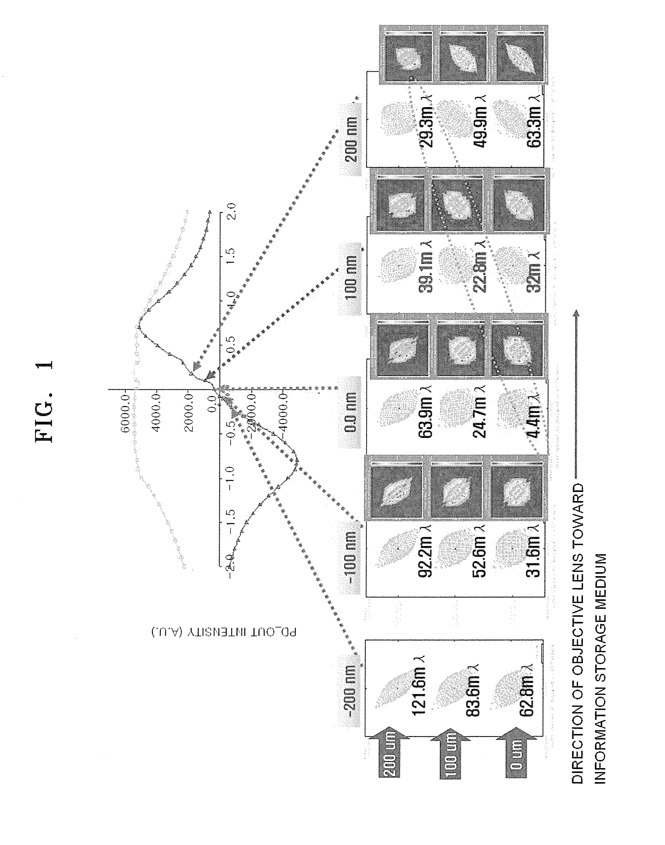
[0031]FIG. 1 is a graph showing an S-curve obtained from signals that are detected by a photodetector while an objective lens is swept when several light beams are emitted from a laser diode (LD) array formed of a plurality of laser diodes (LDs) 100 μm apart from one another. Referring to FIG. 1, changes in aberration that occur on optical spots on an information storage medium according to changes in a working distance of an objective lens and a distribution of a received light beam in the photodetector are illustrated in a lower part thereof. On the optical spot, light emitted from a center light source arranged in line with an optical axis and light...


PUM


Abstract

A multi-channel optical pick-up and a multi-channel optical recording and / or reproducing apparatus employing the same, the multi-channel optical pick-up including: a plurality of light sources including a center light source closest to an optical axis from among the plurality of light sources and at least one off-axis light source farther than the center light source to the optical axis; an objective lens to condense a plurality of light beams respectively emitted from the plurality light sources onto a plurality of tracks of an information storage medium; and an optical path length changing element to compensate for defocus that occurs due to the at least one off-axis light source distanced from the optical axis when a center light beam from the center light source and at least one off-axis light beam from the at least one off-axis light source form spots on the information storage medium.

Description

CROSS-REFERENCE TO RELATED APPLICATION[0001]This application claims the benefit of Korean Patent Application No. 2008-1862, filed Jan. 7, 2008 in the Korean Intellectual Property Office, the disclosure of which is incorporated herein by reference.BACKGROUND OF THE INVENTION[0002]1. Field of the Invention[0003]Aspects of the present invention relate to a multi-channel optical pick-up and a multi-channel optical recording and / or reproducing apparatus employing the same, and more particularly, to a multi-channel optical pick-up that records and / or reproduces data on a plurality of tracks by emitting a plurality of light beams onto different tracks, thereby enhancing a data transmission rate (DTR), and a multi-channel optical recording and / or reproducing apparatus employing the same.[0004]2. Description of the Related Art[0005]Recently, in an optical recording technology, a number of multi-layers of an optical disc (for example, a Blu-ray disc) has increased to expand the capacity of th...

Claims


Application Information

Patent Timeline
IPC IPC(8): G11B7/00G11B7/125G11B7/135
CPCG11B7/127G11B2007/13727G11B7/13922G11B7/1367G11B7/1392G11B7/09
Inventor PARK, KYONGTAEKIM, TAE-KYUNG
Owner SAMSUNG ELECTRONICS CO LTD
Why Eureka
Try Eureka