Steam turbine

Active Publication Date: 2007-11-01
KK TOSHIBA
View PDF5 Cites 7 Cited by
  • Summary
  • Abstract
  • Description
  • Claims
  • Application Information

AI Technical Summary

Benefits of technology

[0013]The present invention provides a steam turbine which can secure the strength of a steam inlet po

Problems solved by technology

If materials having a large difference in coefficient of linear expansion are used to form the turbine casing and the steam pipe, there is a drawback that a large thermal stress is generated in the material-welded portion as a steam temperature increases.
For example, in a case where a steam turbine in which a steam temperature exceeds 650° C. is realized using the same material as those of a related art for the individual portions of the steam turbine, the steam turbine cannot withstand the high-temperature steam.
Therefore, it is advisable to use heat-resisting materials such as a Ni-base alloy and an austenitic material as t

Method used


Image

  • Steam turbine
  • Steam turbine
  • Steam turbine

Examples


first embodiment

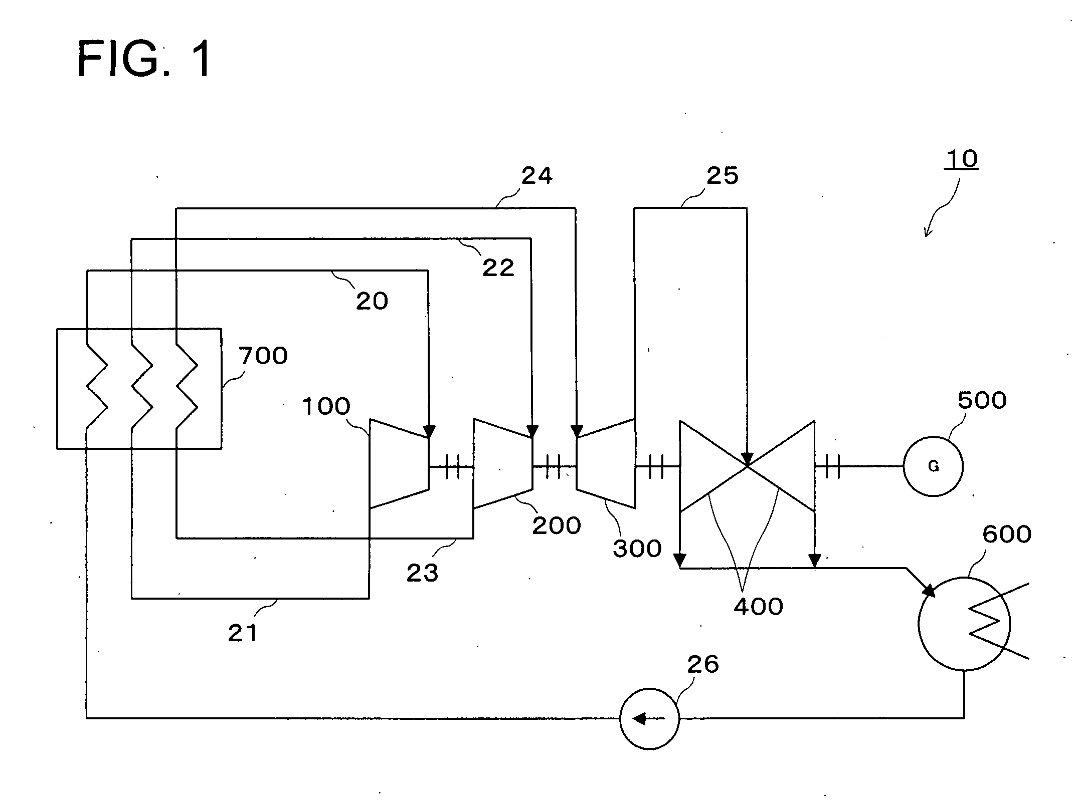
[0022]An overview of a steam turbine power generation system 10 provided with the steam turbine of the first embodiment of the invention will be described with reference to FIG. 1 through FIG. 4.

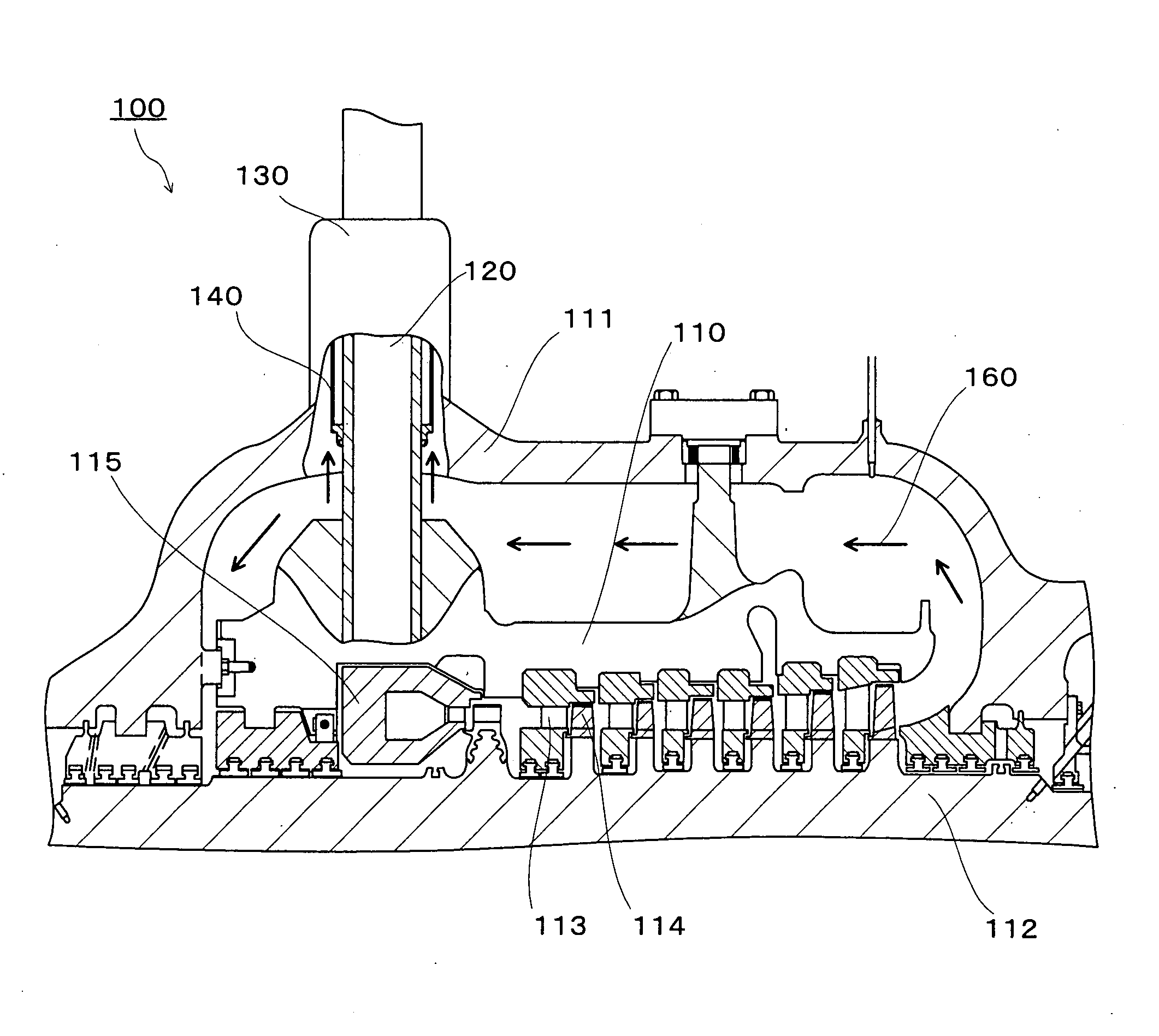
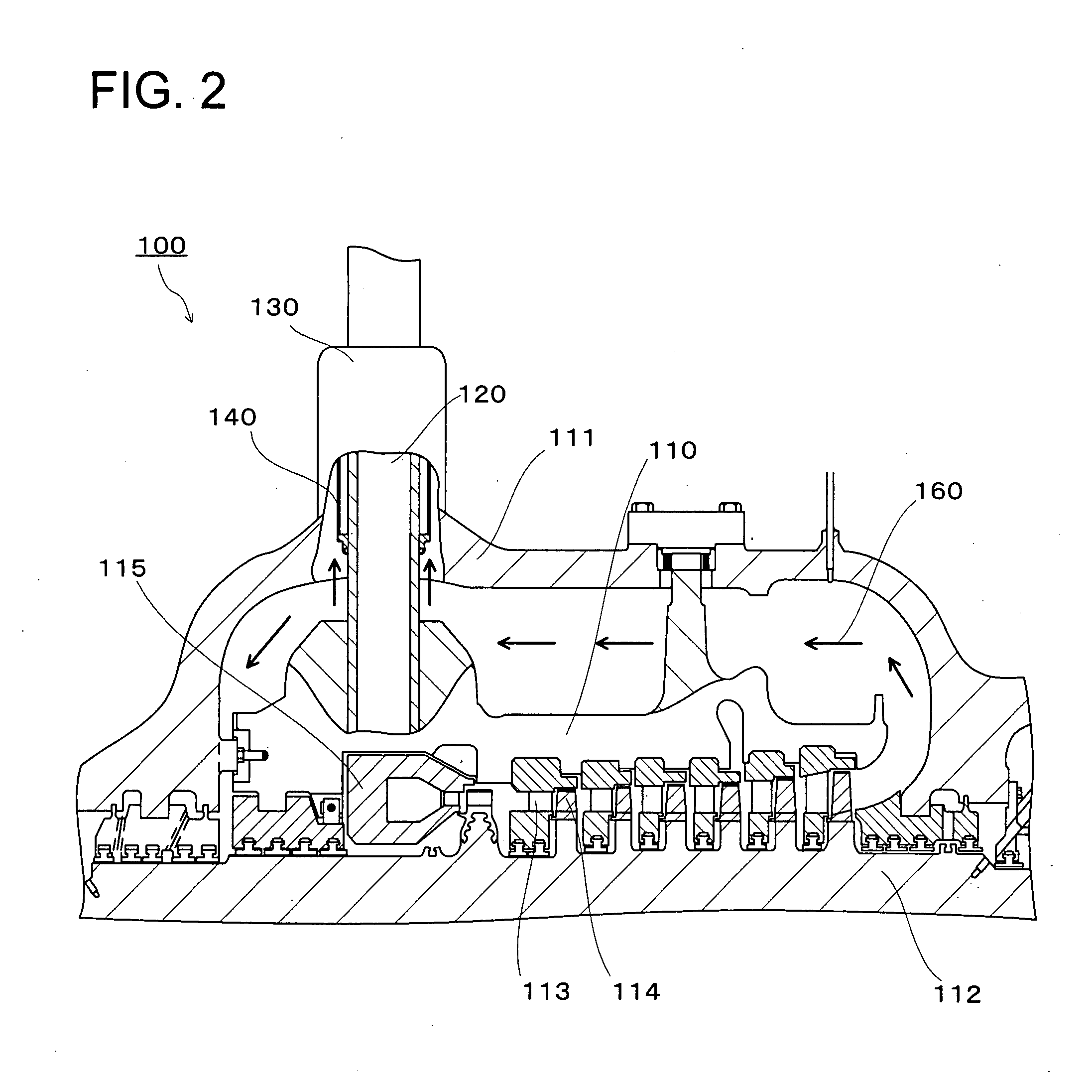
[0023]FIG. 1 is a diagram schematically showing an overview of the steam turbine power generation system 10 provided with the steam turbine according to the first embodiment. FIG. 2 is a diagram showing a cross section of an upper-half casing portion of an extra-high-pressure turbine 100. FIG. 3 is a diagram showing a cross section of a turbine steam inlet portion of the extra-high-pressure turbine 100. FIG. 4 is a diagram showing a cross section of an upper-half casing portion of the extra-high-pressure turbine 100 according to a cooling steam introducing method different from the cooling steam introducing method shown in FIG. 2.

[0024]The steam turbine power generation system 10 is mainly configured of the extra-high-pressure turbine 100, a high-pressure turbine 200, an intermediate-pressur...

second embodiment

[0106]The steam turbine power generation system 10 provided with the steam turbine of the second embodiment according to the invention has the same structure as that of the extra-high-pressure turbine 100 of the first embodiment except that the material form the inner casing 110, the nozzle box 115, the inner steam pipe 120 and the outer steam pipe 130 of the extra-high-pressure turbine 100 of the first embodiment is changed. Here, the material forming the inner casing 110, the nozzle box 115, the inner steam pipe 120 and the outer steam pipe 130 will be described. It should be noted that the ratio of chemical compositions shown below is expressed in “percent by weight”.

(1) Inner Casing 110, Nozzle Box 115, Inner Steam Pipe 120 and Outer Steam Pipe 130

[0107]For the material forming the inner casing 110, the nozzle box 115, the inner steam pipe 120 and the outer steam pipe 130, heat-resisting steel (M4) having the following chemical composition ranges is used. (M4) Heat-resisting ste...

third embodiment

[0132]The steam turbine power generation system 10 provided with the steam turbine of the third embodiment according to the invention has the same structure as that of the extra-high-pressure turbine 100 of the first embodiment except that the material forming the inner casing 110, the nozzle box 115, the inner steam pipe 120 and the outer steam pipe 130 of the extra-high-pressure turbine 100 of the first embodiment is changed. Here, the material forming the inner casing 110, the nozzle box 115, the inner steam pipe 120 and the outer steam pipe 130 will be described. It should be noted that the ratio of chemical compositions shown below is expressed in “percent by weight”.

(1) Inner Casing 110, Nozzle Box 115, Inner Steam Pipe 120 and Outer Steam Pipe 130

[0133]For the material forming the inner casing 110, the nozzle box 115, the inner steam pipe 120 and the outer steam pipe 130, heat-resisting steel (M5) having the following chemical composition ranges is used. (M5) Heat-resisting s...


PUM

PropertyMeasurementUnit
Temperatureaaaaaaaaaa

Abstract

A super steam turbine (100) into which high-temperature steam of 650° C. or more is introduced is provided with an inner steam pipe (120) which is disposed through an inner casing (110) and an outer casing (111), an outer steam pipe (130) which is welded to the outer casing (111) and disposed outside of the inner steam pipe (120) along the inner steam pipe (120) with a prescribed space therebetween, and a radiation heat shielding pipe (140) which is disposed along the inner steam pipe (120) between the inner steam pipe (120) and the outer steam pipe (130) to face a welded portion of at least the outer steam pipe (130), wherein cooling steam (160) is flown between the inner steam pipe (120) and the outer steam pipe (130), respective component parts are made of a suitable heat-resisting steel having prescribed chemical composition ranges.

Description

CROSS-REFERENCE TO RELATED APPLICATIONS[0001]This application is based upon and claims the benefit of priority from the prior Japanese Patent Application No. 2006-125854 filed on Apr. 28, 2006; the entire contents of which are incorporated herein by reference.BACKGROUND[0002]1. Field of the Invention[0003]The present invention relates to a steam inlet portion of a steam turbine into which high-temperature steam flows as a working fluid, and more particularly to a steam turbine which has its respective component parts made of a suitable heat-resisting steel.[0004]2. Description of the Related Art[0005]Energy saving of the thermal power plant is being performed vigorously after the energy crisis, and technology for suppression of the emission of CO2 has being attracting attention in view of the global environmental protection in these years. As part of it, needs for a highly efficient plant are increasing.[0006]To increase power generation efficiency of the steam turbine, it is very e...

Claims


Application Information

Patent Timeline
IPC IPC(8): F04D29/58
CPCC22C1/06F05D2260/2322C22C38/001C22C38/22C22C38/24C22C38/26C22C38/28C22C38/30C22C38/32C22C38/40F01D9/06F01D25/005F01D25/12F01D25/26F05D2220/31C22C19/055
Inventor SUGA, TAKEOISHII, RYUICHITAKAHASHI, TAKEOFUKUDA, MASAFUMI
Owner KK TOSHIBA
Why Eureka
Try Eureka