
Overrunning clutch

a clutch and overrunning technology, applied in the direction of mechanical actuated clutches, interengaging clutches, magnetically actuated clutches, etc., can solve the problems of clutch malfunction, clutch cannot operate reliably, fatigue failure, etc., to extend the service life of the clutch according to this invention, and extend the service life of the clutch

Inactive Publication Date: 2007-11-08
PANG REN
View PDF14 Cites 39 Cited by
  • Summary
  • Abstract
  • Description
  • Claims
  • Application Information

AI Technical Summary

Benefits of technology

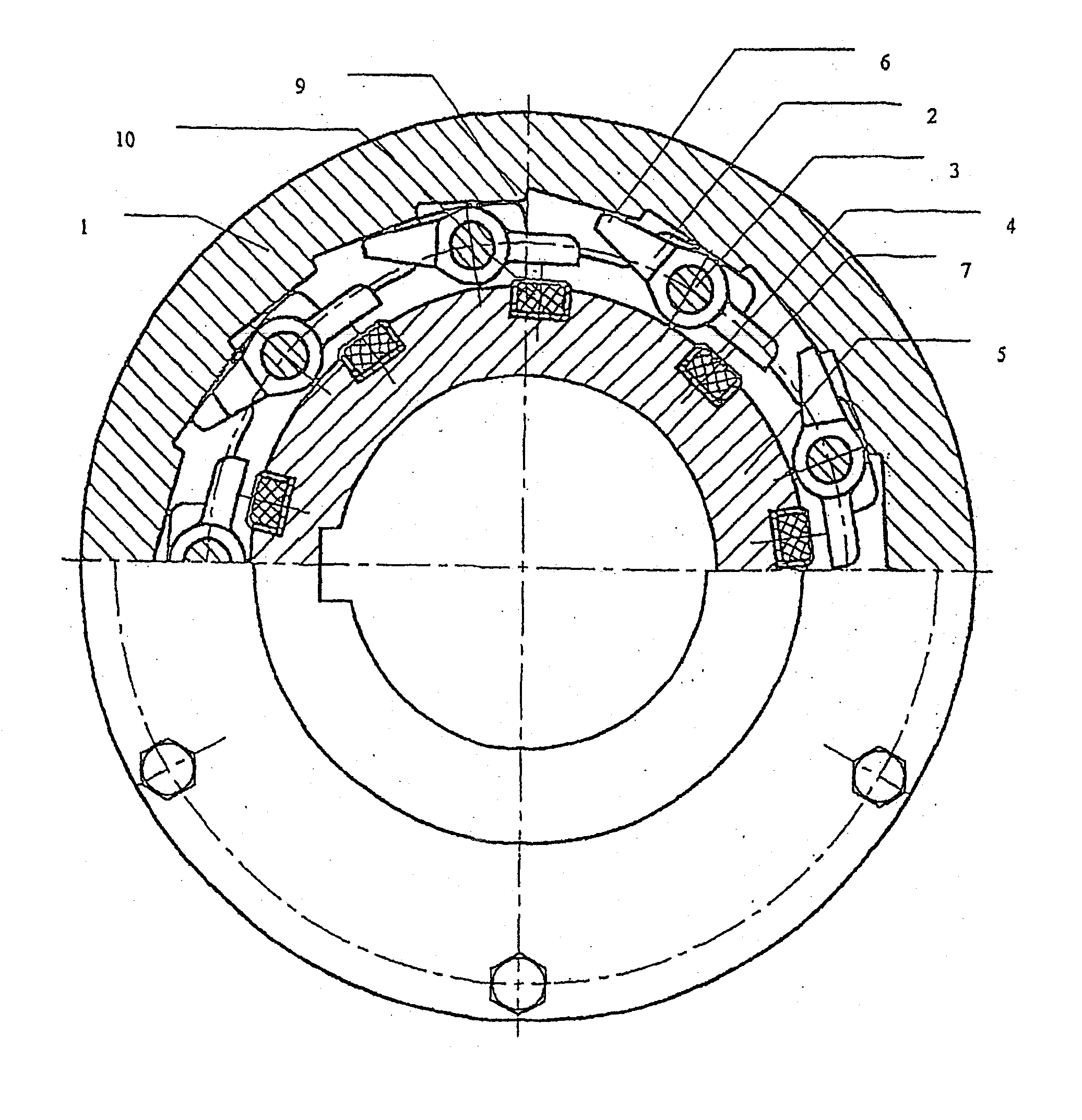
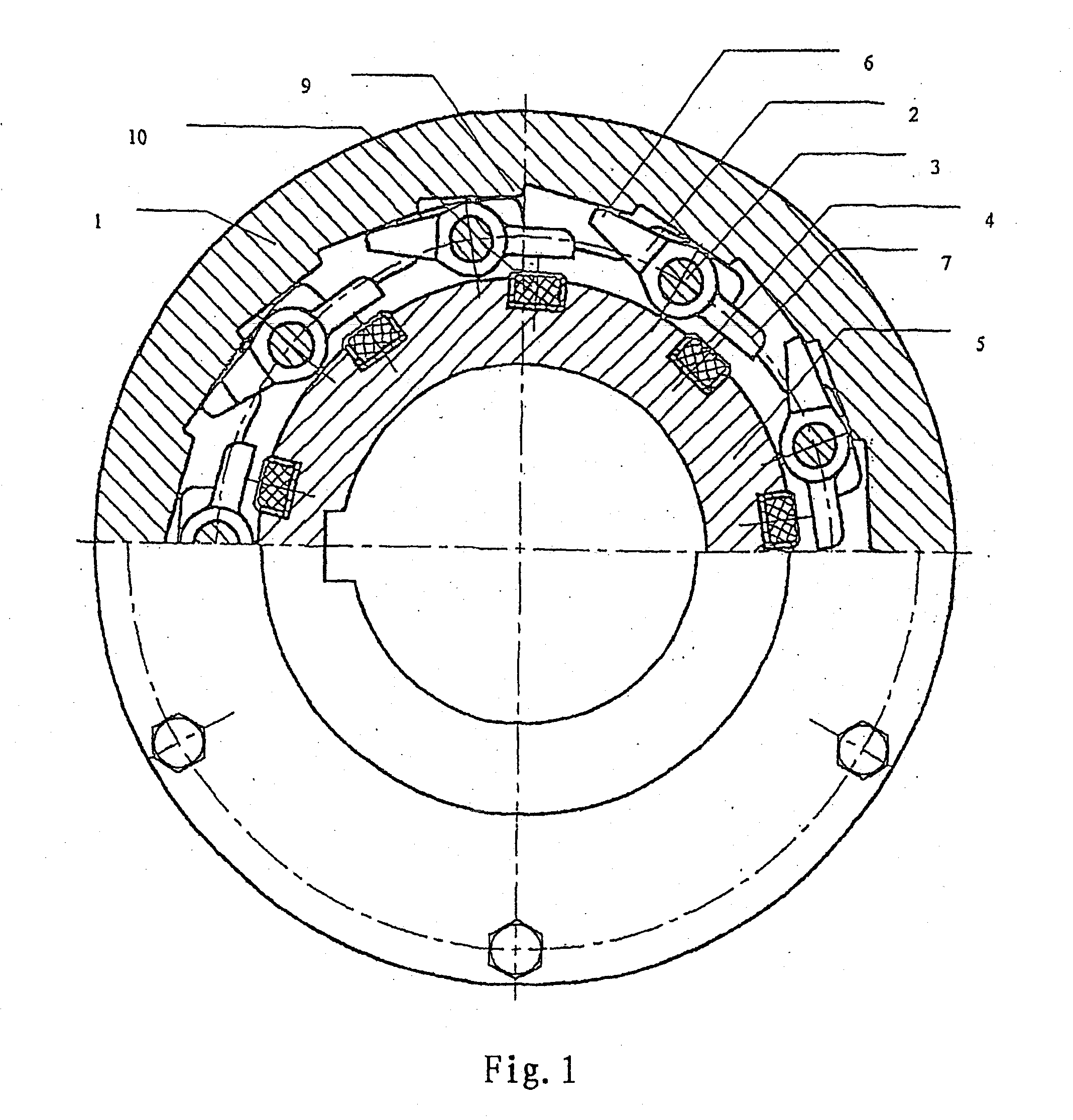
The present invention provides an overrunning clutch that doesn't need a spring to drive the pawl. The clutch includes a ratchet wheel and a plurality of pawls. Each pawl is rotationally supported on a disk member by a shaft. A permanent magnet is fixed on the disk member between the axes of the disk member and the shaft. The magnet is positioned near the tail end of the pawl and is embedded in a mounting sleeve. The distance between the tip of the ratchet end of the pawl and the magnet is slightly larger than the distance between the tip of the tail end and the axis of the through hole. The use of the magnet eliminates the need for springs, reducing fatigue failure and improving the clutch's service life. The magnet is made of ferrite and is not in direct contact with the tail end of the pawl, reducing wear and damage. The distance between the magnet and the tail end of the pawl is designed to prevent the magnet from becoming loose during operation. The clutch's pawl is designed to move reliably and be influenced by a small magnetic force, ensuring the clutch's reliability.

Problems solved by technology

According to the technical solution disclosed in the patent, the ratchet can't operate reliably when the pawls do not rotate flexibly, which is due to the centrifugal force that makes the pawls stretch radially outwardly to mesh with the teeth of the ratchet.
The spring will be fatigue failure quickly and make the clutch be malfunction.
Such contact and impingement cause damage on magnet or make the magnet become hot.
The clutch could be malfunction when the magnet is damaged.
The magnet will shrink when it is heated and then is relaxed, which will also make the clutch be malfunction.

Method used


Image

  • Overrunning clutch
  • Overrunning clutch

Examples


Embodiment Construction

[0018] The number 1 indicates a ratchet wheel in FIG. 1, the ratchet teeth 9 are provided on the inner side of the ratchet wheel 1. The disk member 5 is coaxial with ratchet wheel 1 and can rotate relatively to the ratchet wheel 1. A number of pawls 2 are shown in FIG. 1, the practical number of the pawls can be determined according to the working condition. Each of the pawls 2 is rotationally supported on the disk member 5 by a shaft 3 through a through hole 8. The pawl 2 is a long and thin element made of ferromagnetism material such as steel. The pawl 2 includes a ratchet end 6 which engages with the teeth of said ratchet wheel, and a tail end 7 is opposing to the ratchet end 6. The distance a from the tip of the ratchet end 6 to the center of the shaft 3 is larger than the distance b from the tip of the tail end 7 to the center of the shaft 3. In this embodiment, a equals to 40 mm, b equals to 36 mm. The ratio of a / b can ensure the pawl 2 to engage with ratchet teeth 9 on the ra...


PUM


Abstract

An overrunning clutch comprising a ratchet wheel (1) and a plurality of pawls (2) is disclosed. Each of the pawls (2) is rotationally supported on a disk member (5) by a shaft (3). The clutch is characterized by a permanent magnet (4) being fixed on the disk member (5) between the axes of the disk member (5) and the shaft (3) and facing the tail end of each pawl (2). Because each of the pawls are not driven by a spring in the clutch, the clutch could not be malfunction due to the fatigue failure of the spring in the case of frequent heavy load.

Description

CROSS REFERENCE TO RELATED APPLICATIONS [0001] This application is a continuation of application Ser. No. 10 / 381,352 filed on Sep. 22, 2003, which claims priority from PCT International Application No. PCT / CN01 / 01038 filed Jun. 25, 2001, which claims priority from China Application No. 00254031.2 filed Sep. 29, 2001 and China Application No. 01129231.8 filed Jun. 18, 2001, the complete disclosures of which are hereby incorporated by reference.TECHNICAL FIELD [0002] The present invention relates to an overrunning clutch, and more particularly, to a clutch that is in frequently overrunning condition with heavy load. BACKGROUND ART [0003] An inertial centrifugal ratchet is disclosed in Chinese Utility Model patent CN91208227.5, wherein a magnetic ring is provided under the ratchet. The pawls stretch radially outwardly in the direction effected by the centrifugal force when gears are turning so as to mesh with the teeth of the ratchet. According to the technical solution disclosed in th...

Claims


Application Information

Patent Timeline
Patent Type & Authority Applications(United States)
IPC IPC(8): F16D27/01F16D41/30F16D41/12
CPCF16D41/12
Inventor JIN, FENGHE, JIANJUNPANG, REN
Owner PANG REN
Learn More