

Stormwater bioretention filtration system with overflow/bypass capability
- Summary
- Abstract
- Description
- Claims
- Application Information
AI Technical Summary
Benefits of technology
Problems solved by technology
Method used
Image

Examples
first embodiment
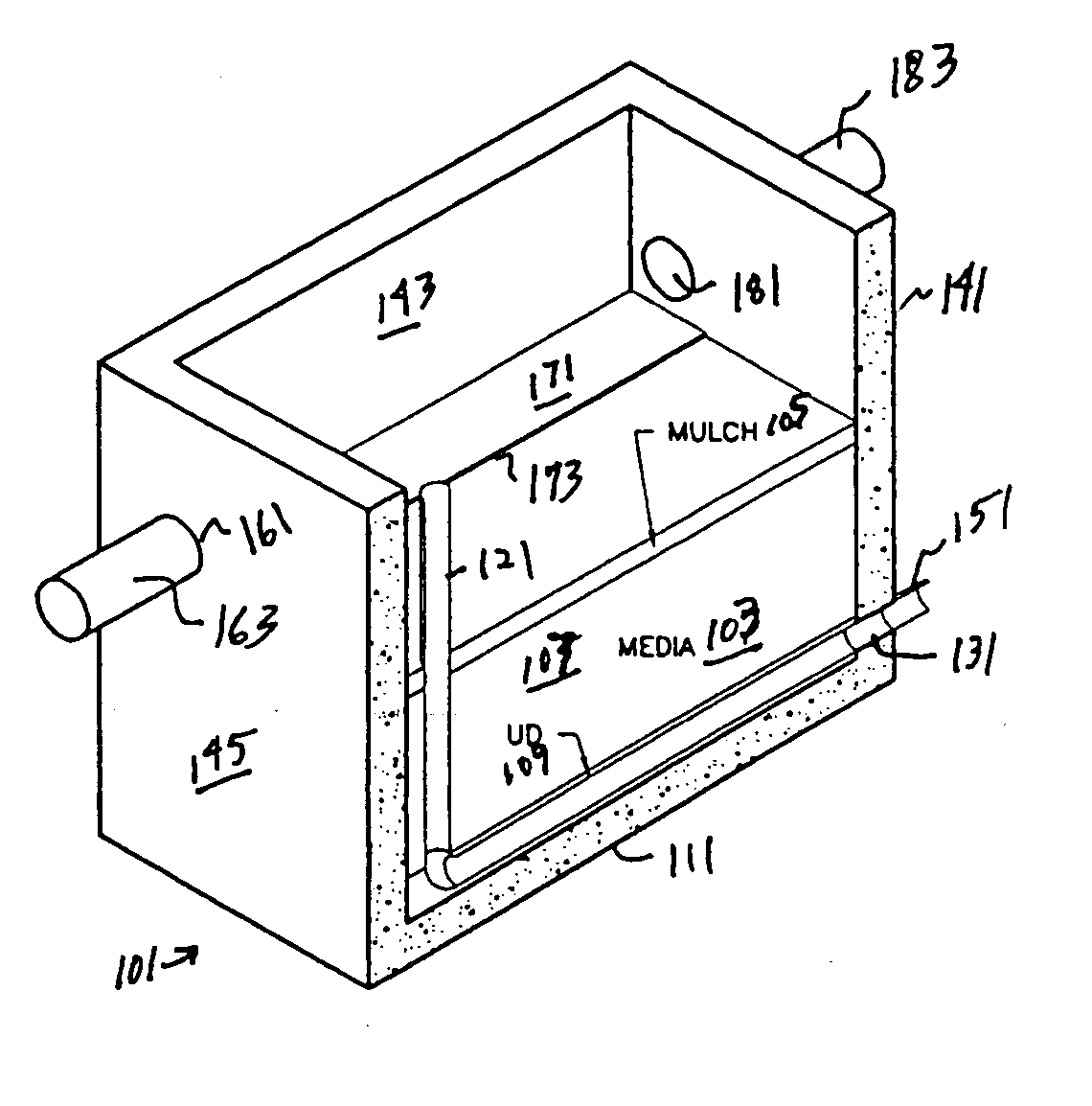
[0027] the present invention is depicted in FIGS. 3(a)-3(d). A stormwater treatment system is depicted comprising a substantially water impermeable treatment container 101, preferably made of concrete. The treatment container 101 includes sidewalls 141, 143, 145, 147, a bottom wall 111, and a top slab 125 that is at least partially open to the atmosphere. Centrally disposed in the top slab is an opening 126 through which a tree grate (not shown) is inserted. This is similar to the tree grate 27 shown in FIG. 1. Plant material can grow out of the opening into the atmosphere. The container size is similar in plan view to the prior art container of FIG. 1, but preferably is taller from top to bottom by about 2′ to accommodate the inlet and outlet pipe openings to be described. Filter media 103, i.e., a soil mixture 107, is located within the container along with a mulch layer 105 overlying the soil mixture. The filter media is designed to be effective for bioretention and may be that d...
PUM
| Property | Measurement | Unit |
|---|---|---|
| Flow rate | aaaaa | aaaaa |
| Diameter | aaaaa | aaaaa |
| Height | aaaaa | aaaaa |
Abstract
Description
Claims
Application Information