Holster for charging pectorally implanted medical devices

a pectoral implanted medical device and charging ring technology, applied in the field of holsters for charging pectoral implanted medical devices, can solve the problems of disadvantageous electric wires perforating the skin, large inconvenience, and risk of infection, and achieve the effect of reducing the risk of infection

Active Publication Date: 2007-11-08
MEDTRONIC INC
View PDF67 Cites 145 Cited by
  • Summary
  • Abstract
  • Description
  • Claims
  • Application Information

AI Technical Summary

Problems solved by technology

Having electrical wires that perforate the skin is disadvantageous due, in part, to the risk of infection.
Further, continuously coupling patients to an external power for therapy is, at least, a large inconvenience.
However, such single cell batteries usually do not supply the lasting power required to perform new therapies in newer implantable medical devices.
This is not desirable due to the need to explant and re-implant the implantable medical device or a portion of the device.
First, the inductive coupling, while inductively inducing a current in the secondary coil, also has a tendency to heat surrounding components and tissue.
The amount of heating of surrounding tissue, if excessive, can be deleterious.
Since heating of surrounding tissue is limited, so also is the amount of energy transfer that can be accomplished per unit time.
This attachment may impair the patient's mobility and limit the patient's comfort.
Third, the amount of charging or recharging can be limited by the amount of time required for charging or recharging.
Since the patient is typically inconvenienced during such charging or recharging, there is a practical limit on the amount of time during which charging or recharging should occur.
Hence, the size of the internal power source can be effectively limited by the amount of energy that can be transferred within the amount of charging time.
Implantable medical devices, external power sources, systems and methods have not always provided the best possible system or method for allowing the patient to be ambulatory during energy transfer and / or charging.
Physical limitations related to the energy transfer and / or charging apparatus and methods as well as necessary efficiencies of operation can effectively limit the patient's ability to move around during such energy transfer and / or charging and can deleteriously affect patient comfort.

Method used


Image

  • Holster for charging pectorally implanted medical devices
  • Holster for charging pectorally implanted medical devices
  • Holster for charging pectorally implanted medical devices

Examples


Embodiment Construction

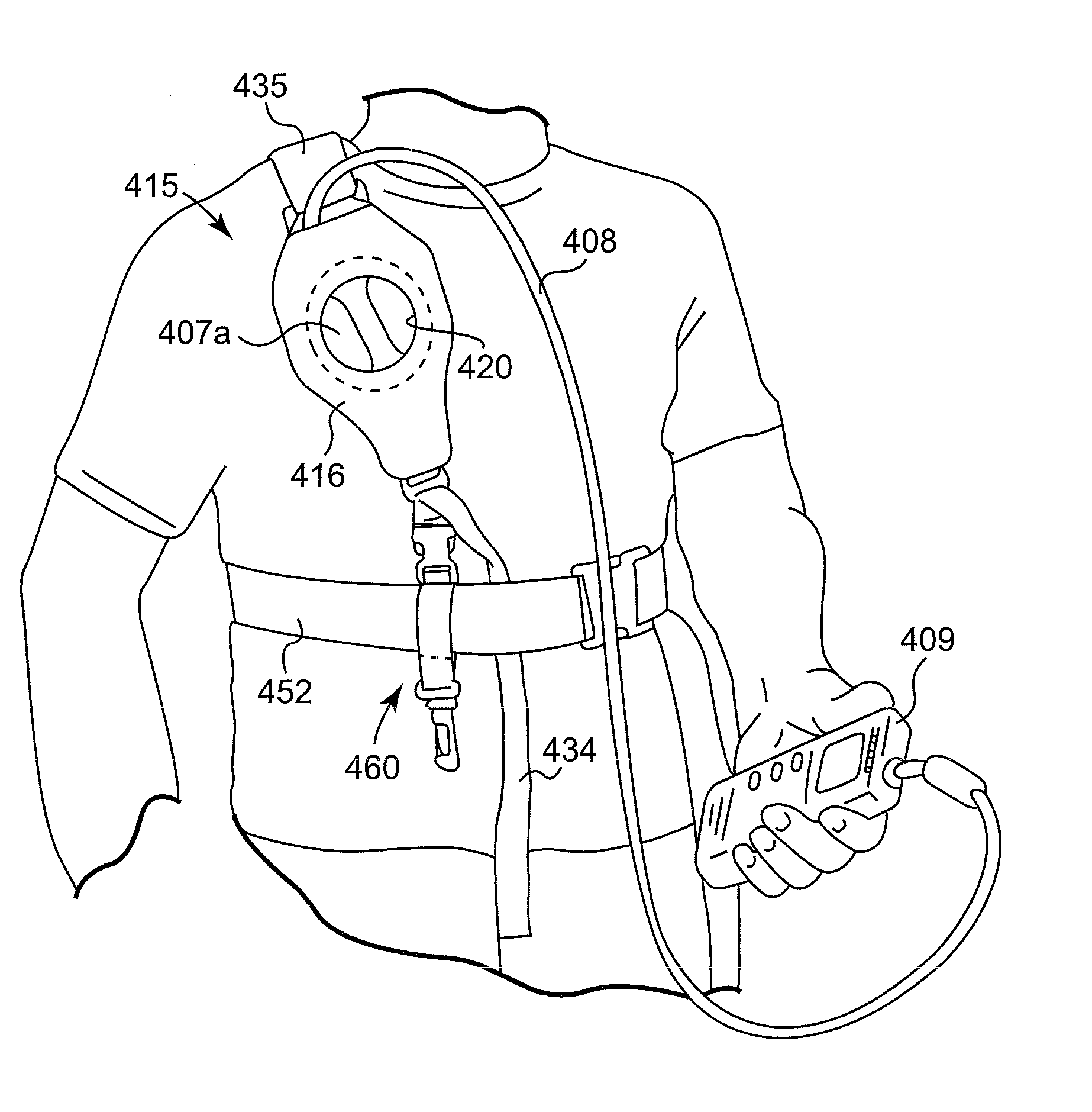
[0045] A preferred embodiment holster for charging pectorally implanted medical devices constructed according to the principles of the present invention is designated by the numeral 115 in the drawings, another embodiment holster for charging pectorally implanted medical devices constructed according to the principles of the present invention is designated by the numeral 215 in the drawings, another embodiment holster for charging pectorally implanted medical devices constructed according to the principles of the present invention is designated by the numeral 315 in the drawings, and another embodiment holster for charging pectorally implanted medical devices constructed according to the principles of the present invention is designated by the numeral 415 in the drawings.

[0046] The holsters 115, 215, 315, and 415 may be used to charge any suitable pectorally implanted medical device. The term “charge” refers to any type of charge including, but not limited to, an initial charge and...


PUM


Abstract

A holster that may be donned in a first configuration for charging a pectorally implanted medical device on the patient's right side, a second configuration for charging a pectorally implanted medical device on the patient's left side, or a third configuration for use as a waist belt for charging a pectorally implanted medical device on either side of the patient.

Description

[0001] This application is a continuation-in-part application of U.S. patent application Ser. No. 11 / 414,155, filed Apr. 28, 2006, which is incorporated herein by reference.FIELD OF THE INVENTION [0002] The present invention relates to a holster for charging pectorally implanted medical devices. BACKGROUND OF THE INVENTION [0003] Implantable medical devices for producing a therapeutic result in a patient are well known. An example of such an implantable medical device includes implantable neurostimulators used for the treatment of movement disorders such as Parkinson's Disease, essential tremor, and dystonia. Other examples of such implantable medical devices include implantable drug infusion pumps, implantable cardioverters, implantable cardiac pacemakers, implantable defibrillators, and cochlear implants. Of course, it is recognized that other implantable medical devices are envisioned that utilize energy delivered or transferred from an external device. [0004] A common element in...

Claims


Application Information

Patent Timeline
Patent Type & Authority Applications(United States)
IPC IPC(8): H02J7/00A45F3/02
CPCA61N1/3787A61N1/08
Inventor PHILLIPS, WILLIAM C.LEWIS, CHARLES R. JR.SAHASRABUDHE, RAJEEV M.
Owner MEDTRONIC INC
Why Eureka
Try Eureka