Ophthalmologic imaging apparatus

a technology of ophthalmologic imaging and imaging apparatus, which is applied in the field of ophthalmologic imaging apparatus, can solve the problems of difficult to achieve the high-power image and the low-power image at the same time and with the same wavelength in these conventional optical devices, and to verify which site on the retina is measured

Inactive Publication Date: 2007-11-08
KK TOPCON
View PDF3 Cites 28 Cited by
  • Summary
  • Abstract
  • Description
  • Claims
  • Application Information

AI Technical Summary

Benefits of technology

[0016] According to the present invention, it can provide an ophthalmologic imaging apparatus that can achieve both a low-power image and a high-power image at the same time. Furthermore, according to the present invention, it can provide an ophthalmologic imaging apparatus that can specify the position of the high-power image on the basis of the low-

Problems solved by technology

However, it has been hitherto difficult to achieve both the high-power image and the low-power image at the same time and with the same wavelength in these conventional optical devices.
Furthermore, when conventional Adaptive Optics is applied to

Method used


Image

  • Ophthalmologic imaging apparatus
  • Ophthalmologic imaging apparatus
  • Ophthalmologic imaging apparatus

Examples


Embodiment Construction

1. Outline

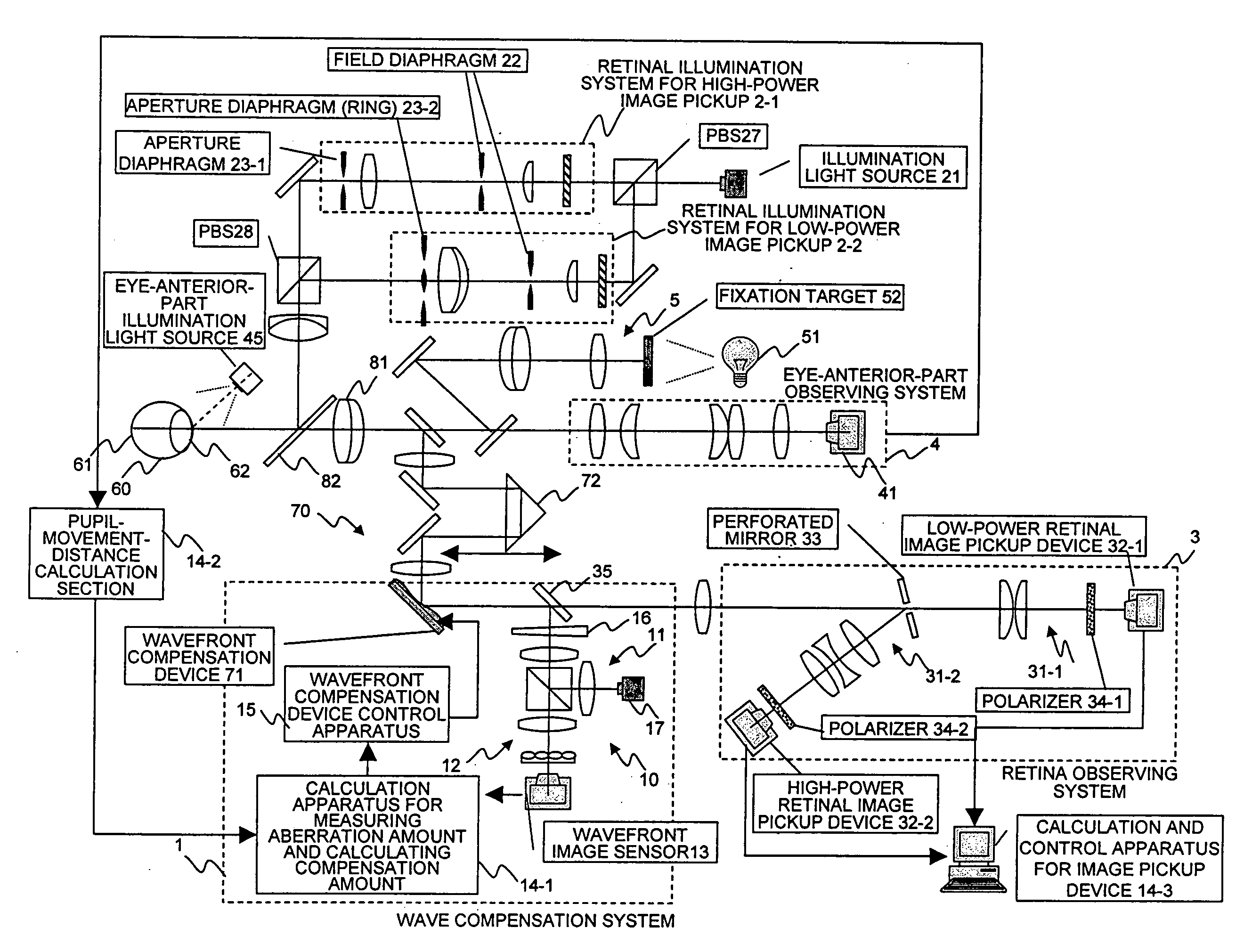
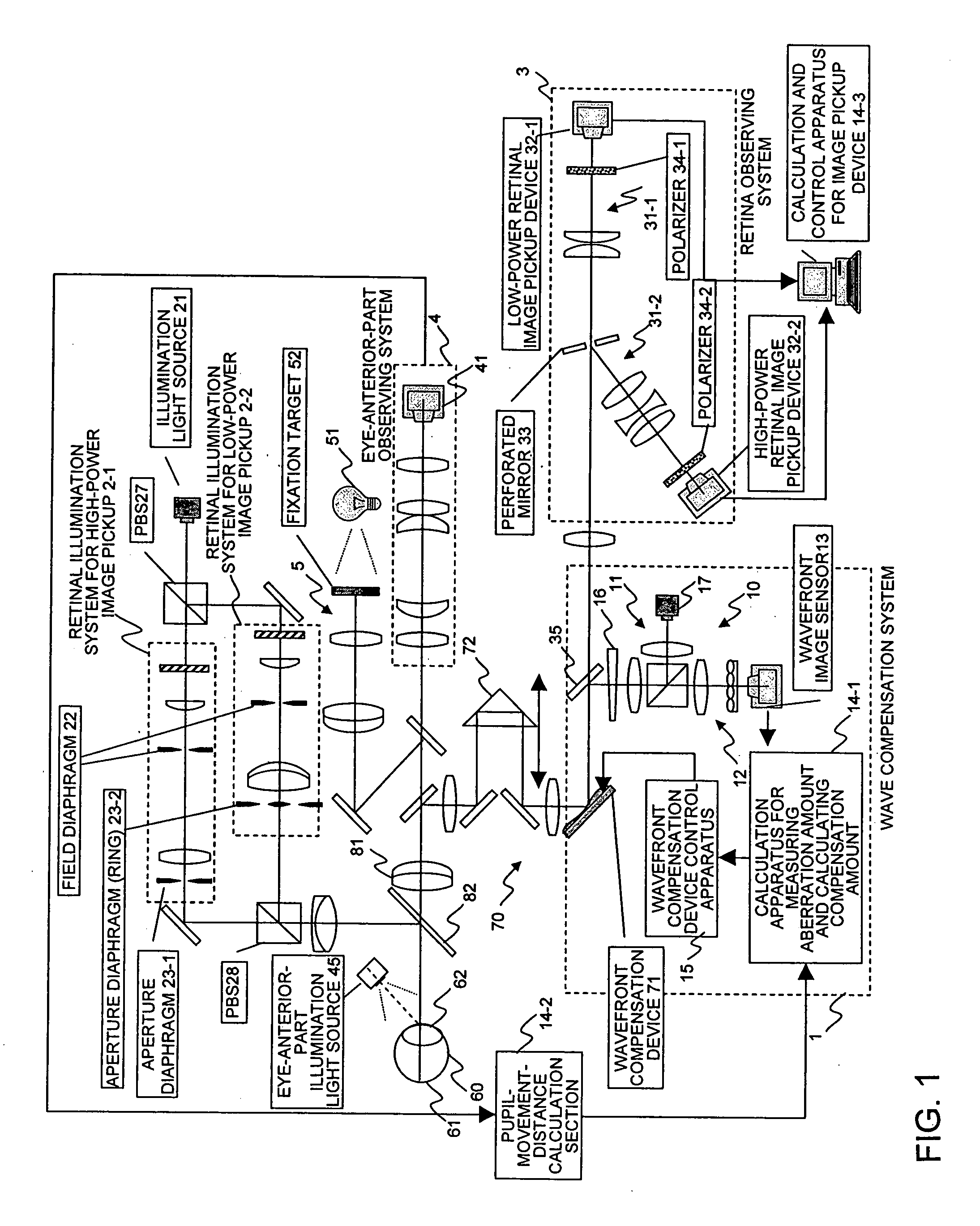
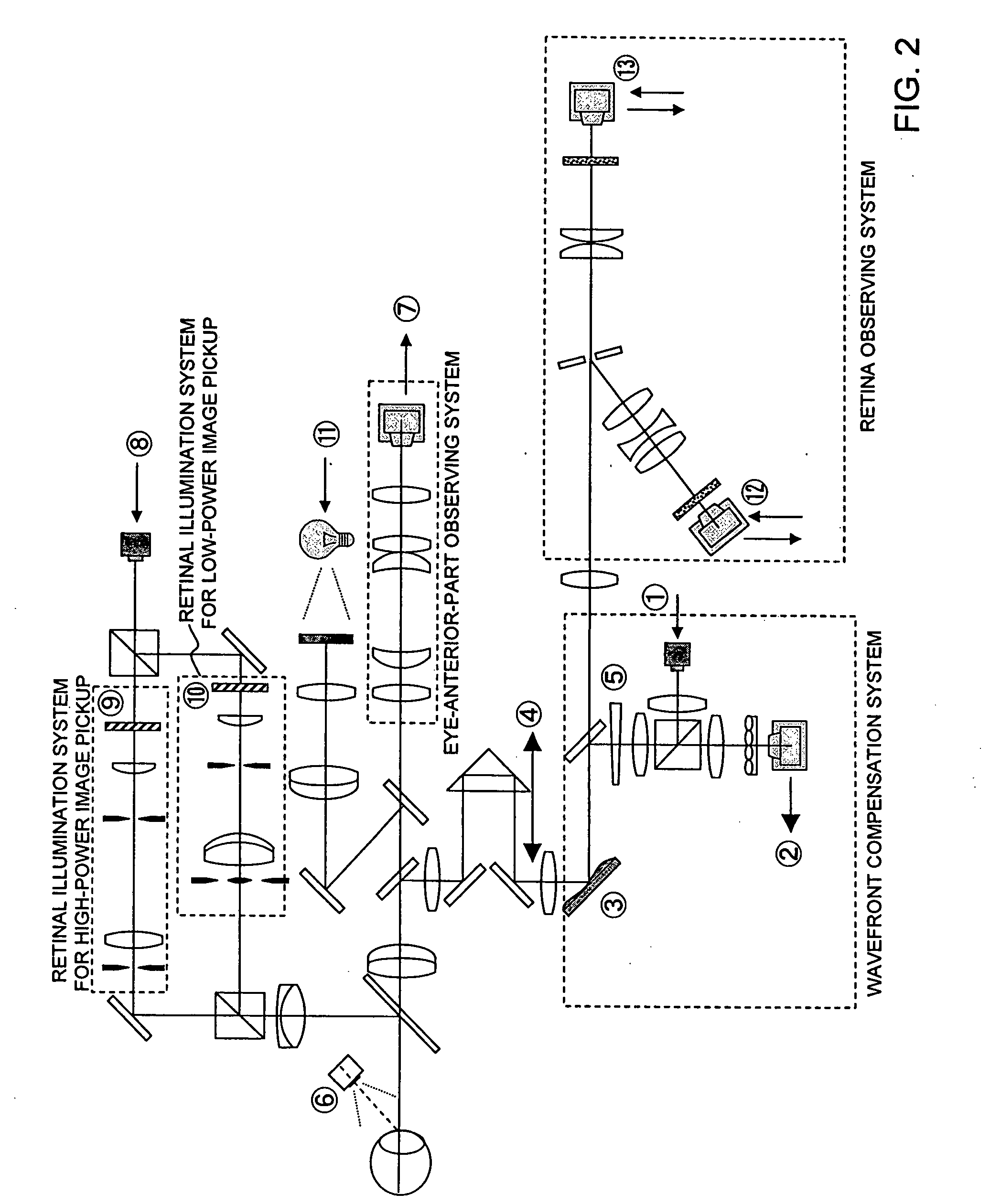
[0025] This embodiment relates to an Adaptive Optics retina camera characterized in that a high-power (high magnifying power) retinal image and a low-power (low magnifying power) retinal image can be picked up at the same time. This embodiment can simultaneously achieve an image from the Adaptive Optics system which can observe retina with high resolution and an image from a finder system which can acquire an image with wide range by using polarization and pupil division. In this embodiment, the high power (high magnifying power) and the low-power (low magnifying power) are relative magnifying powers, and represent different two magnifying powers (first magnifying power and second magnifying power). For example, the low power may be set to a magnifying power for achieving an image of the overall retina, and the high power may be set to a magnifying power for achieving an image of a local position of the retina, however, they are not limited.

2. Optical Arrangement

[0026...


PUM


Abstract

Light from a light source is divided into S-polarization and P-polarization light. The P-polarization light is incident to a retinal illumination system for high-power image and the S-polarization light is incident to a retinal illumination system for low-power image. These lights are set center illumination and ring illumination by aperture diaphragms. Reflection light flux from a cornea under the high-power retina illumination light passes through the center of a perforated mirror, and thus light reflected from the retina and the perforated mirror is received through a high-power optical system to achieve an excellent retinal image having no flare. Likewise, reflection light flux from the cornea under the low-power retina illumination light is reflected from the perforated mirror, and thus light reflected from the retina and passing through the center of the hole is received through a low-power optical system to achieve an excellent retinal image having no flare.

Description

BACKGROUND OF THE INVENTION [0001] 1. Field of the Invention [0002] The present invention relates to an ophthalmologic imaging apparatus, and particularly to an ophthalmologic imaging apparatus that can pick up both a high-power retinal image and a low-power retinal image at the same time. [0003] 2. Description of the Related Art [0004] The following technologies have been disclosed by the assignee of present application. An eye-characteristic measurement apparatus which compensates for aberrations of an eye under measurement by a compensation optical section and measures precisely a minute aberration remaining after compensation is disclosed, for example, in Japanese Unexamined Patent Application Publication No. 2004-113405, No. 2004-159779, and No. 2004-159784. A retina observation apparatus which compensates a light beam reflected by an eye under measurement in order to improve retinal image quality and obtains an optimal image is disclosed, for example, in Japanese Unexamined Pa...

Claims


Application Information

Patent Timeline
IPC IPC(8): A61B3/10
CPCA61B3/156
Inventor YAMAGUCHI, TATSUOMIHASHI, TOSHIFUMI
Owner KK TOPCON
Why Eureka
Try Eureka