Multi-protocol network interface card

a network interface and multi-protocol technology, applied in the field of multi-protocol computer network systems, can solve problems such as reducing system performance, affecting system performance, and affecting system performance,

Inactive Publication Date: 2007-11-08
NETWORK APPLIANCE INC
View PDF19 Cites 53 Cited by
  • Summary
  • Abstract
  • Description
  • Claims
  • Application Information

AI Technical Summary

Problems solved by technology

One problem may occur when a plurality of user nodes communicate a plurality of data packets to the Ethernet switch in random bursts, which can cause the buffer associated with the Ethernet switch to overflow.
When the buffer of the Ethernet switch overflows, subsequently communicated data packets may be dropped or lost.
Temporarily halting receipt of data packets in the Ethernet Switch until the buffer can be emptied avoids the problem of dropping or losing data, however, this approach significantly reduces system performance (e.g. by introducing undesirable latencies into the systems).
The Fibre Channel switch can also experience similar problems related to buffer overflows as that described above with respect to the Ethernet switch.
It is not sufficient to simply increase the size of the buffer(s) to accommodate the data packets because this can result in long delays in moving the data packets in and out of the buffer, which also introduces system latencies and seriously degrades system performance.
Further, large buffers may be costly and difficult to design in practice, especially for high-speed systems.
Another problem in the above-described conventional connectionless switched communication system is related to the significant overhead processing that is carried out by the servers to convert or re-format the data packets back and forth between the Ethernet format (e.g. suitable for communication over the LAN) and the Fibre Channel format (e.g. suitable for communication over the SAN).
Therefore, an unsolved need remains for a data communication system that can support a plurality of protocols and reduce or eliminate the overhead processing that is carried out by the servers to convert or re-format the data packets back and forth between the Ethernet protocol and the Fibre Channel protocol.

Method used


Image

  • Multi-protocol network interface card
  • Multi-protocol network interface card
  • Multi-protocol network interface card

Examples


Embodiment Construction

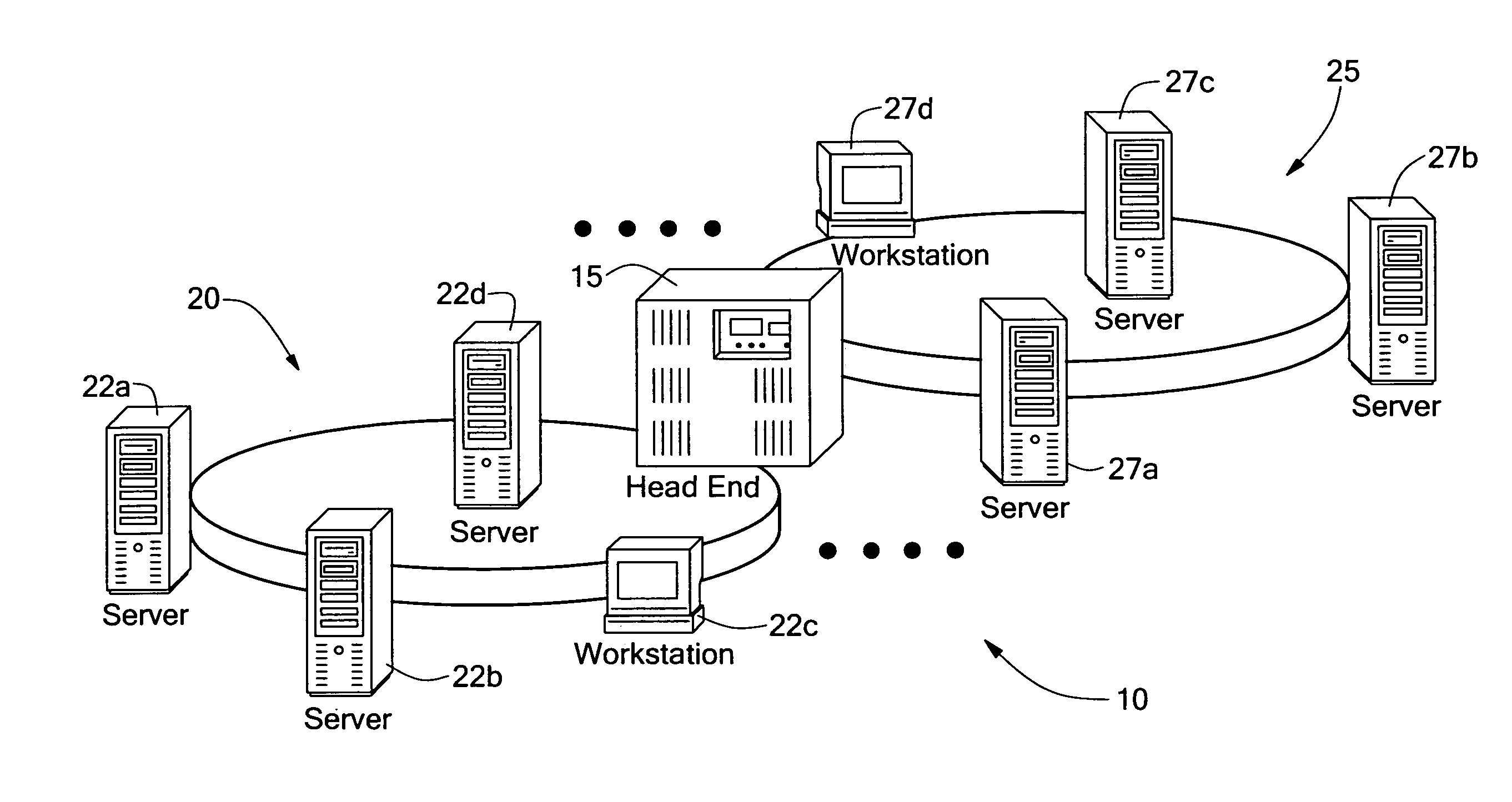
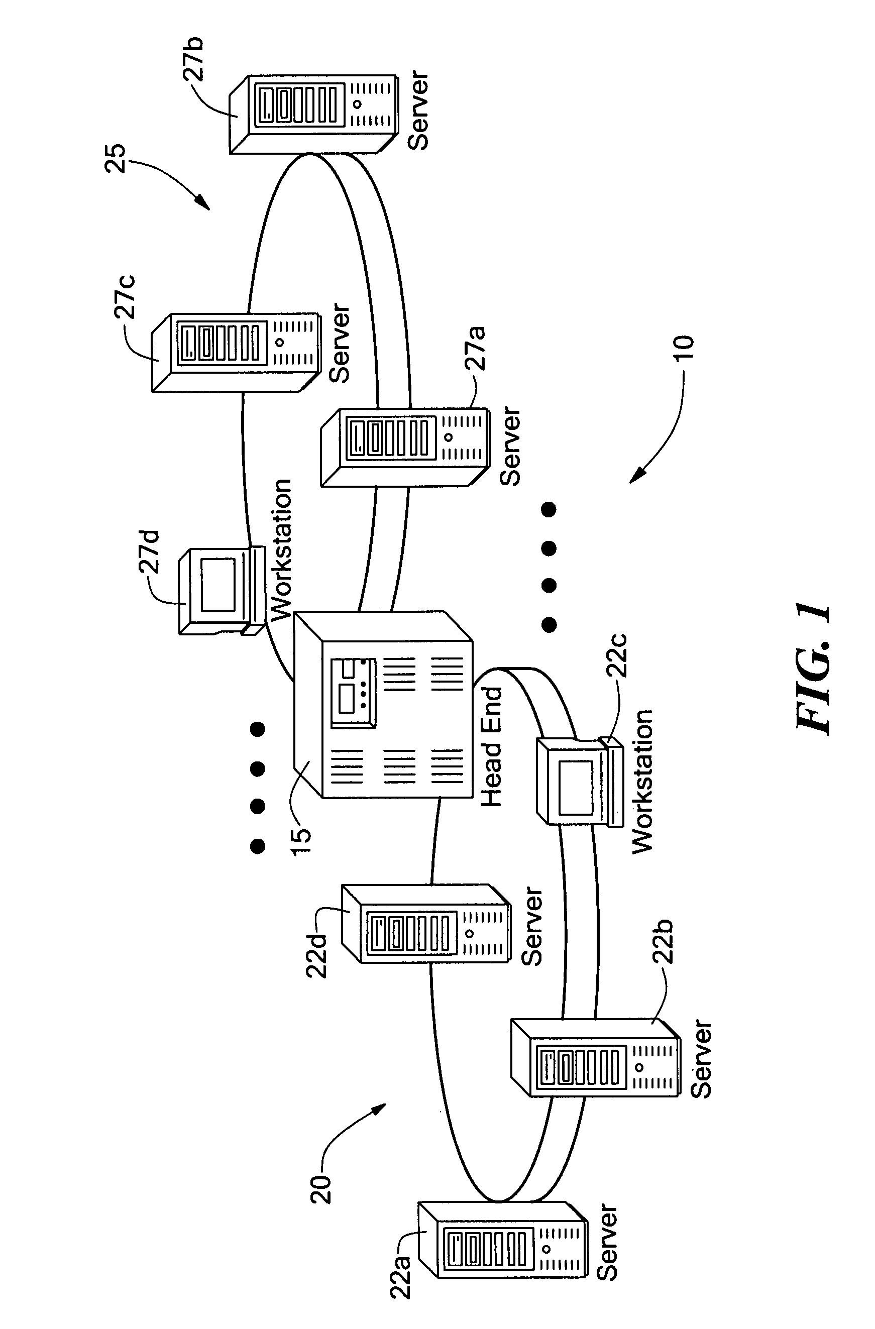
[0026] Before referring to the figures describing the present invention, some introductory concepts and terminology are described. A method and apparatus for a communications network that illustrates the present invention is described. Although the networking system is sometimes described herein in the particular context of a fiber-optic local-area network (LAN), it should be understood that the networking system can also be used in a metropolitan-area network (MAN), or a wide-area network (WAN), or a Passive Optical Network (PON), or a storage-area network (SAN). Furthermore, it should be understood that the transmission medium is not limited to fiber-optic transmission media (e.g. fiber optic) cables. Rather, non-optical transmission media (including wireless transmission media) may also be used. The optical networking system will be referred to as the ONS. The computers, processors or storage systems attached to the ONS will be referred to as “ONS nodes” or more simply “NODEs.” I...


PUM


Abstract

A method and apparatus for a communications network that executes a medium access control (MAC) protocol that permits multiple access to a shared medium or shared switching fabric. The MAC protocol uses a BANDWIDTH_ALLOCATOR to regulate access to the network by sending a permission message to a NODE, allowing it to transmit to a specific set of NODEs for a specific length of time. The medium and switching fabric can carry one or more protocols, each of varying framing format and native bitrate. The switching fabric provides a connection-oriented bufferless data transport service that preserves frame ordering. An illustrative embodiment uses a slotted master / slave time-division multiplexed access (TDMA) scheme to allow flexible provisioning of network bandwidth.

Description

[0001] This application is a continuation application of U.S. patent application Ser. No. 10 / 196,336, which was filed on Jul. 16, 2002 which claims the benefit of U.S. patent application Ser. No. 09 / 994,475 filed on Jan. 26, 2001 and also claims benefit of U.S. Provisional Patent Application No. 60 / 306,651, filed on Jul. 18, 2001, and 60 / 305,724 filed on Jul. 16, 2001.FIELD OF THE INVENTION [0002] The invention relates to a multi-protocol computer network system. More particularly, the present invention relates to a multi-protocol network interface card included in each node of a plurality of nodes includes on the multi-protocol computer network system. BACKGROUND OF THE INVENTION [0003] A conventional connectionless switched communication system may be used to communicate information within a local area network (“LAN”) and within a storage area network (“SAN”). The LAN can include a plurality of user nodes or computers (e.g. personal computers) coupled to a plurality of servers, vi...

Claims


Application Information

Patent Timeline
Patent Type & Authority Applications(United States)
IPC IPC(8): H04L12/28
CPCH04L47/10H04L47/22H04L49/357H04L49/351H04L49/30
Inventor CHINN, STEPHEN R.CIANCAGLINI, GENE M.GAROFALO, MICHAEL M.HART, JAMES A.LUPINACCI, MICHAELMARICHAL, PAULMOORES, JOHN D.OLIVEIRA, GUYPARIKH, SALIL A.PARQUETTE, MARK R.PROULX, WILLIAMPROULX, DONALDRYDEEN, MICHAEL
Owner NETWORK APPLIANCE INC
Why Eureka
Try Eureka