
X-ray ct apparatus and x-ray ct scanning method

Inactive Publication Date: 2007-11-08
GE MEDICAL SYST GLOBAL TECH CO LLC
View PDF9 Cites 31 Cited by
  • Summary
  • Abstract
  • Description
  • Claims
  • Application Information

AI Technical Summary

Benefits of technology

[0049]The X-ray CT apparatus of the present invention has advantageous effects that can bring about in that an improvement in timing control on the transition to an actual scan for constant agent synchronous imaging at a helical scan or a variable pitch helical scan or a helical shuttle scan, an improvement in reliability of a monitor scan, and a reduction in exposure can be realized.
that can bring about in that an improvement in timing control on the transition to an actual scan for constant agent synchronous imaging at a helical scan or a variable pitch helical scan or a helical shuttle scan, an improvement in reliability of a monitor scan, and a reduction in exposure can be realized.

Problems solved by technology

Therefore, a problem arises in that the timing provided to start the actual scan become slower (Japanese Unexamined Patent Publication No. 2006-051234 for example).
Therefore, there is a trend to more grow a problem about X-ray needless exposure.
Further, the timing might be missed and reliability has been demanded upon the measurement of the average CT value in the region of interest at the monitor scan for the contrast agent synchronous photography.
In this case, however, there might be a case in which the timing be missed in the case of the average CT value in the whole region of interest.

Method used


Image

  • X-ray ct apparatus and x-ray ct scanning method
  • X-ray ct apparatus and x-ray ct scanning method
  • X-ray ct apparatus and x-ray ct scanning method

Examples


first embodiment

[0161]It should however be noted that since the contrast agent becomes a significant burden on the subject, the amount of the contrast agent is reduced as much as possible to perform the photography. Therefore, there is a demand to inject the contrast agent into the subject with suitable timing and perform X-ray CT imaging at the timing with a suitable delay time.

[0162]The following are known as a method for recognizing this contrast-agent injection and the suitable timing

[0163]1. Bolus Tracking Method

[0164]It is a method of monitoring a change in CT value at a region of interest ROI after the injection of a contrast agent and starting an actual scan with the most suitable timing when exceeds an established threshold value.

[0165]2. Test Injection Method

[0166]Prior to an actual scan, this test is that a pre-scan using a small amount of contrast agent is performed to grasp the rate of the bloodstream. Based on this result, this actual scan determine the optimum timing and proceed phot...

second embodiment

[0482]At the actual scan preparatory operation 3 shown in FIG. 34 of the first embodiment and the actual scan preparatory operation 4 shown in FIG. 35, the retention or holding period in which the X-ray tube 21 and the multi-row X-ray detector 24, and the cradle 12 are being relatively stopped in the z-axis direction, exists in the times [t3, t4] and times [t6, t7].

[0483]When such three-dimensional image reconstruction as shown in FIG. 7 is used in particular, such retention as described above exists when z=z0 and Z=Z7 at the times [t34, t4] and times [t6, t7] shown in FIG. 34 or 35. If the retention period in which the X-ray tube 21 and multi-row X-ray detector 24, and the cradle 12 are being relatively stopped, is for example, fan angles +180° or more, or fan angles +180° or so, then the tomogram image reconstruction range can be extended outside up to about half the X-ray beam width at maximum as compared with the moving range of each of the X-ray tube 21 and multi-row X-ray dete...

third embodiment

[0484]In the first embodiment, needless exposure has been reduced by avoiding the application of X rays to the non image-reconstructed portions by the X-ray collimator 23.

[0485]In the second embodiment, the tomogram image reconstructable range is extended to the X-ray radiation range by the three-dimensional image reconstruction using the application of X rays during the retention period in which the X-ray tube 21 and the multi-row X-ray detector 25 and the cradle 12 are being relatively stopped in the z-axis direction, thereby reducing needless exposure.

[0486]FIG. 44A is a diagram showing an X-ray radiation range for a conventional helical scan, and FIG. 44B is a diagram showing an X-ray radiation range for a helical scan in which a scan gantry 20 of the third embodiment is tilted. At the conventional helical scan, the portions corresponding to diagonally-shaped portions shown at the scan start and end in FIG. 44A have been used as for X-ray radiation unused in image reconstruction...


PUM


Abstract

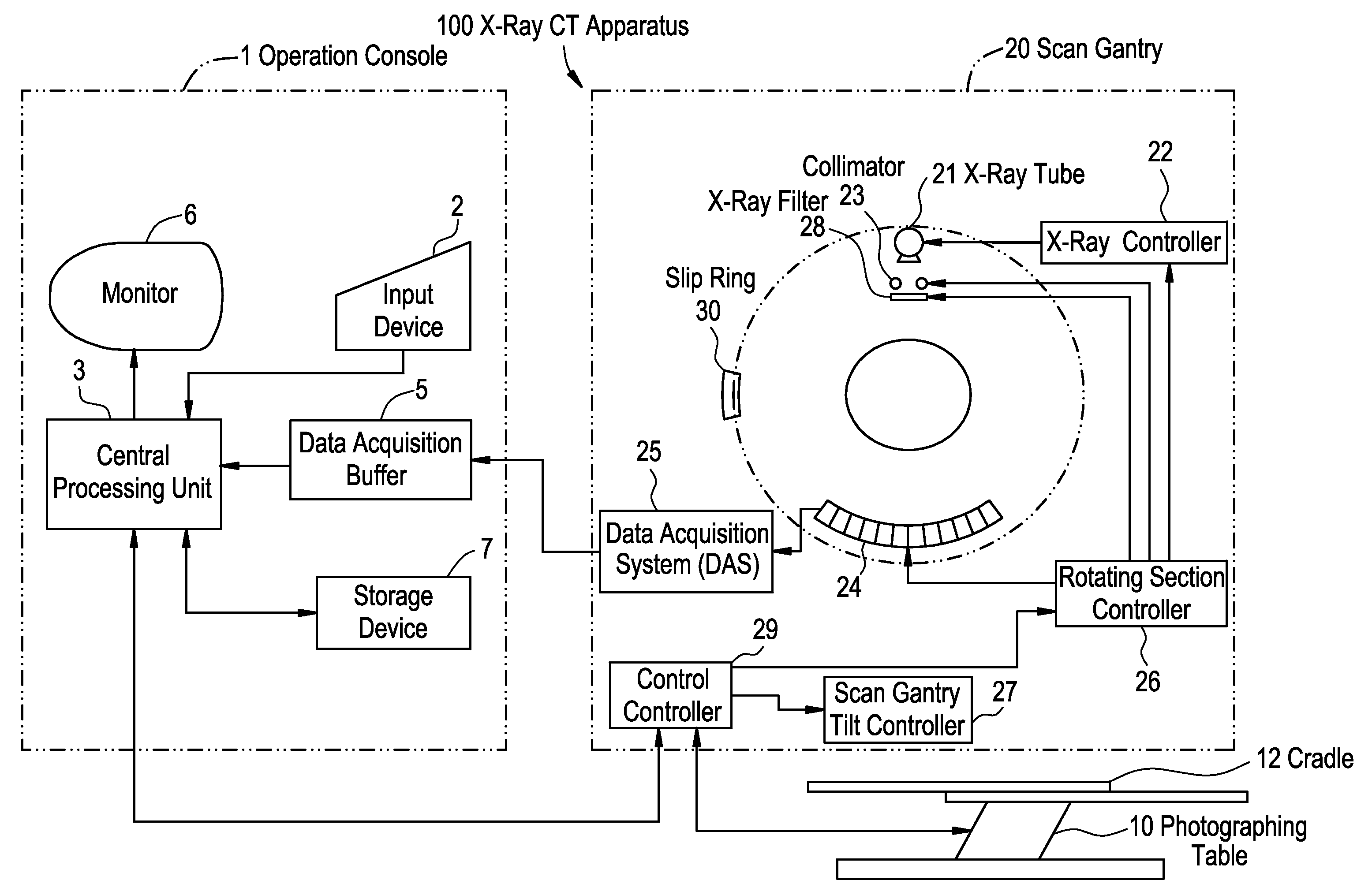
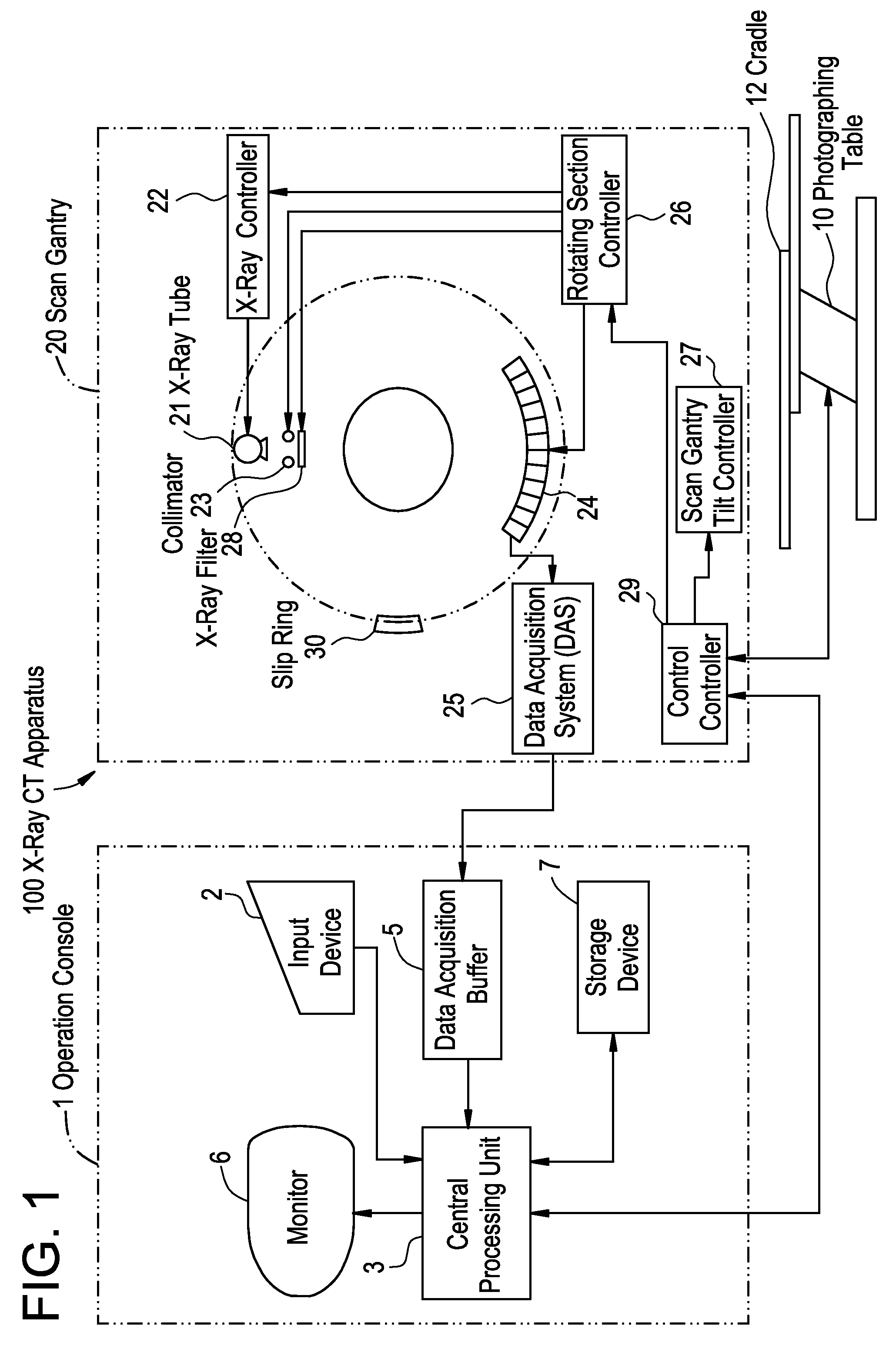
The present invention provides an X-ray CT apparatus which realizes an improvement in timing control on transition to an actual scan for contrast agent synchronous imaging and its reliability, and an improvement in reduction in X-ray exposure. The X-ray CT apparatus includes an X-ray source, an X-ray detector disposed so as to be opposite to the X-ray source with a subject implanted with a contrast agent being interposed therebetween, a contrast agent synchronous imaging device which performs acquisition of projection data upon the start of the actual scan for the contrast agent synchronous photography while relative operations between the subject and the X-ray source, and the X-ray detector are being accelerated in a predetermined direction, and image reconstructing device which reconstructs a tomographic image, based on the projection data.

Description

CROSS REFERENCE TO RELATED APPLICATIONS[0001]This application claims the benefit of Japanese Patent Application No. 2006-118604 filed Apr. 23, 2006.BACKGROUND OF THE INVENTION[0002]The present invention relates to an X-ray CT apparatus which realizes speeding-up of timing control on contrast agent synchronous imaging in a medical X-ray CT (Computed Tomography) apparatus or the like.[0003]Upon contrast agent synchronous imaging or photography of an X-ray CT apparatus, the mean or average CT value in each region of interest is measured at predetermined time intervals at a monitor scan for the contrast agent synchronous imaging, and the monitor scan is terminated when the average CT value exceeds a certain predetermined threshold value. Then, a cradle is moved to the position of an actual scan to carry out the actual scan. Since the actual scan uses a helical scan, the cradle has been moved to the actual scan position in consideration of to a run-up distance necessary for the cradle ac...

Claims


Application Information

Patent Timeline
IPC IPC(8): A61B6/00G01N23/00G21K1/12H05G1/60
CPCA61B6/032A61B6/469A61B6/027A61B6/488A61B6/542A61B6/481
Inventor NISHIDE, AKIHIKOIISAKU, SHINICHISEKIGUCHI, JUNKO
Owner GE MEDICAL SYST GLOBAL TECH CO LLC
Learn More