
Heated glass panels and methods for making electrical contact with electro-conductive films

Inactive Publication Date: 2007-11-08
RADIANT GLASS INDS
View PDF26 Cites 16 Cited by
  • Summary
  • Abstract
  • Description
  • Claims
  • Application Information

AI Technical Summary

Benefits of technology

[0008] A glass panel assembly according to one embodiment of the invention may include a first glass sheet having an electro-conductive film provided thereon and a conductor positioned at a location on the electro-conductive film. A retainer engages an edge portion of the first glass sheet and the conductor so that the retainer applies a compressive pressure to the conductor. The compressive pressure enhances electrical contact between the conductor and the electro-conductive film.

Problems solved by technology

While commonly used configurations for such heated glass panels work well were the amount of heat produced is modest, such as, for example, in applications wherein the formation of condensation is to be avoided, considerable problems arise in applications wherein greater amounts of heat are to be produced.
However, it has proven difficult to provide an electrical connection between the power source and the electro-conductive film that is capable of reliably providing the higher currents required to produce significant amounts of heat.
While bus bars formed from such thin metal foils have been used with success in low power applications (e.g., panel de-fogging), they are not capable of handling the higher currents involved in situations where the heated glass panels are to provide a significant amount of heat.
While thicker conductors could be used, it has proven difficult to provide uniform contact between the thicker conductors and the electro-conductive film.
For example, small gaps or spaces between the conductors and the film may result in uneven heating of the film.
In addition, such small gaps or spaces may result in the formation of arcs or sparks between the conductors and the film, which can be deleterious to the film, the conductors, or both.
While such systems have been used to produce conductors capable of handling the higher currents required for higher power dissipation, they tend to be difficult to implement, requiring expensive equipment and highly trained personnel.
In addition, thickness variations in the sprayed-on metal coating may create hot spots and non-uniformities in the electrical current in the film, both of which can adversely affect the performance of the system.

Method used


Image

  • Heated glass panels and methods for making electrical contact with electro-conductive films
  • Heated glass panels and methods for making electrical contact with electro-conductive films
  • Heated glass panels and methods for making electrical contact with electro-conductive films

Examples


Embodiment Construction

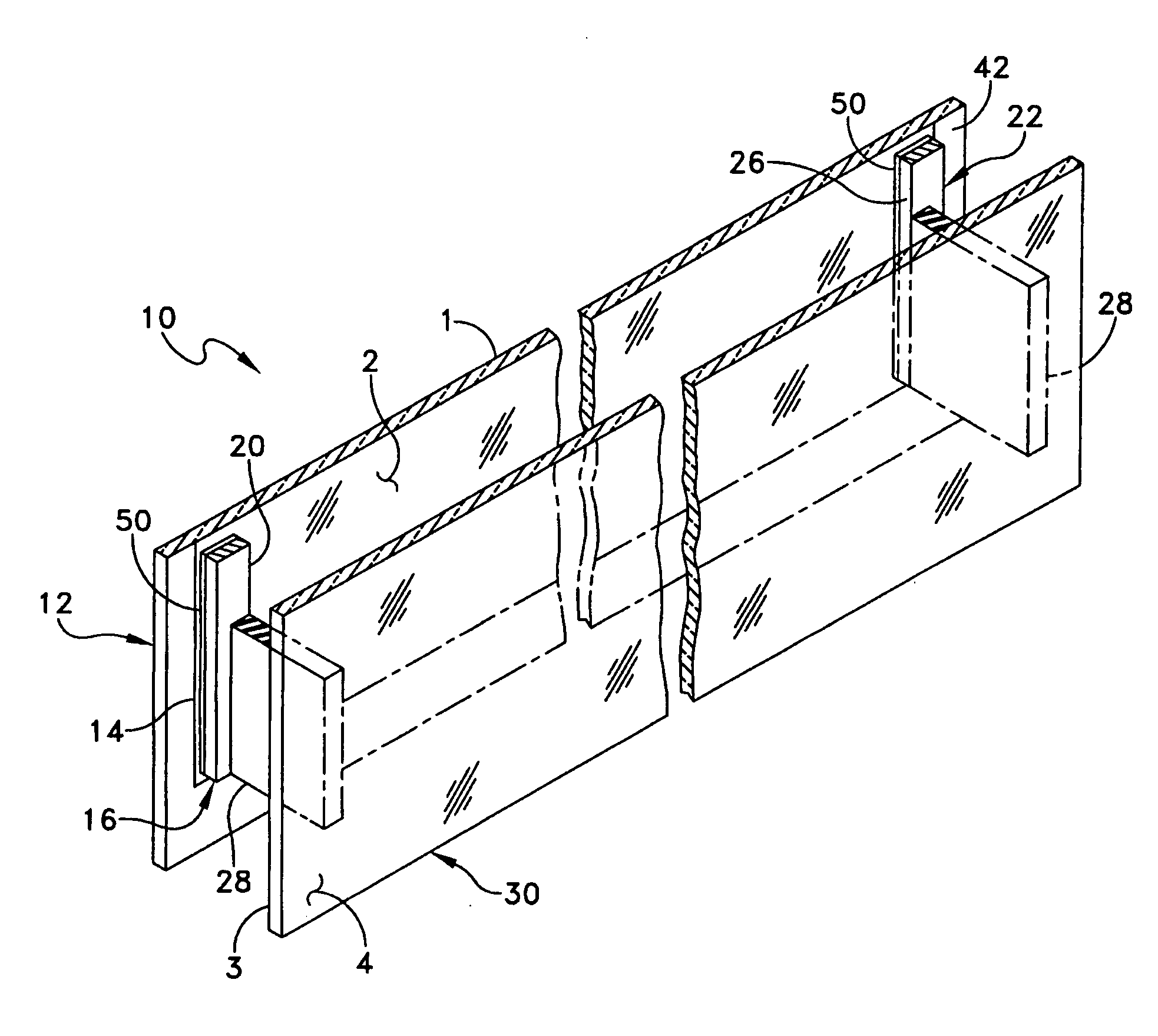
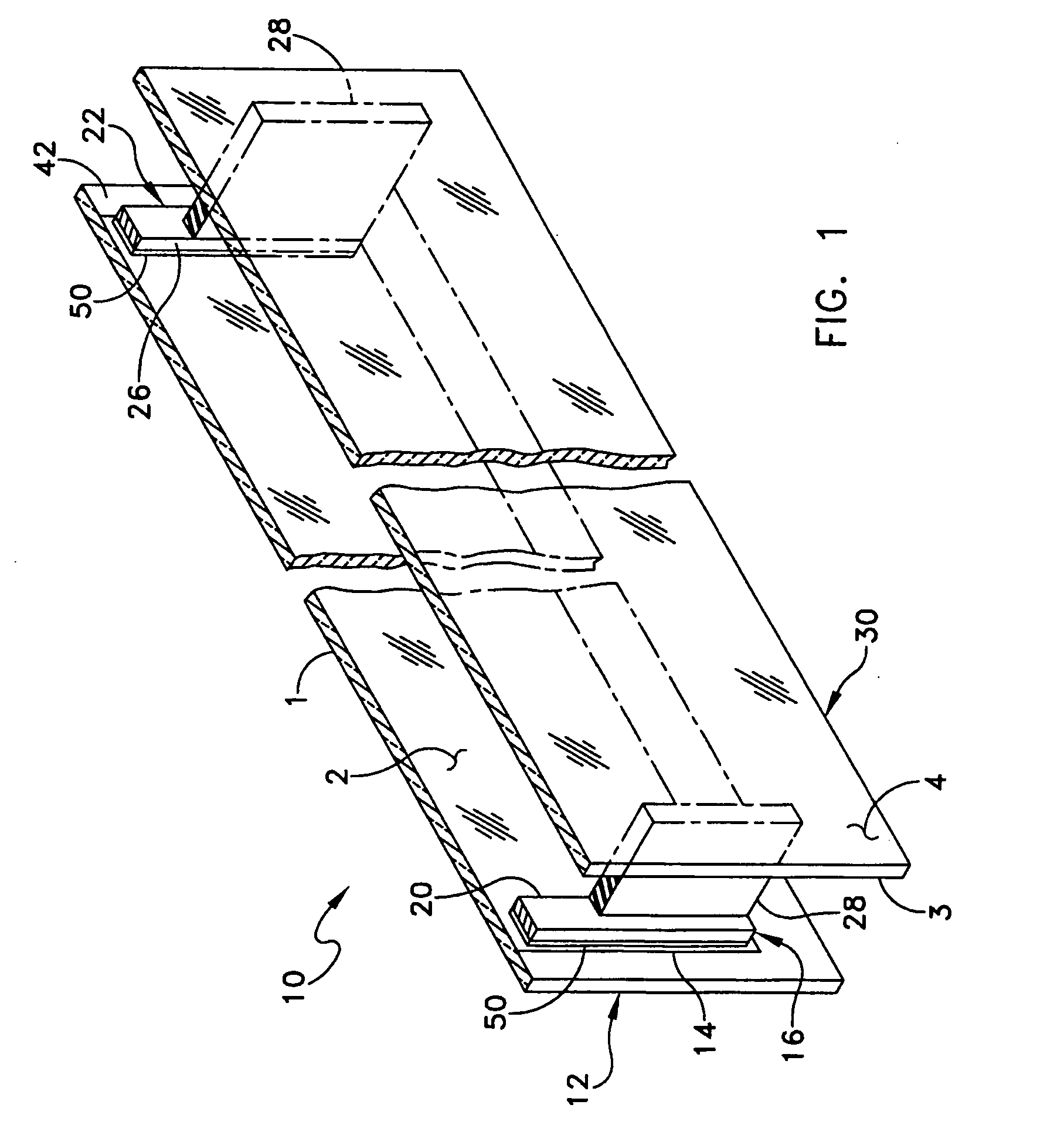
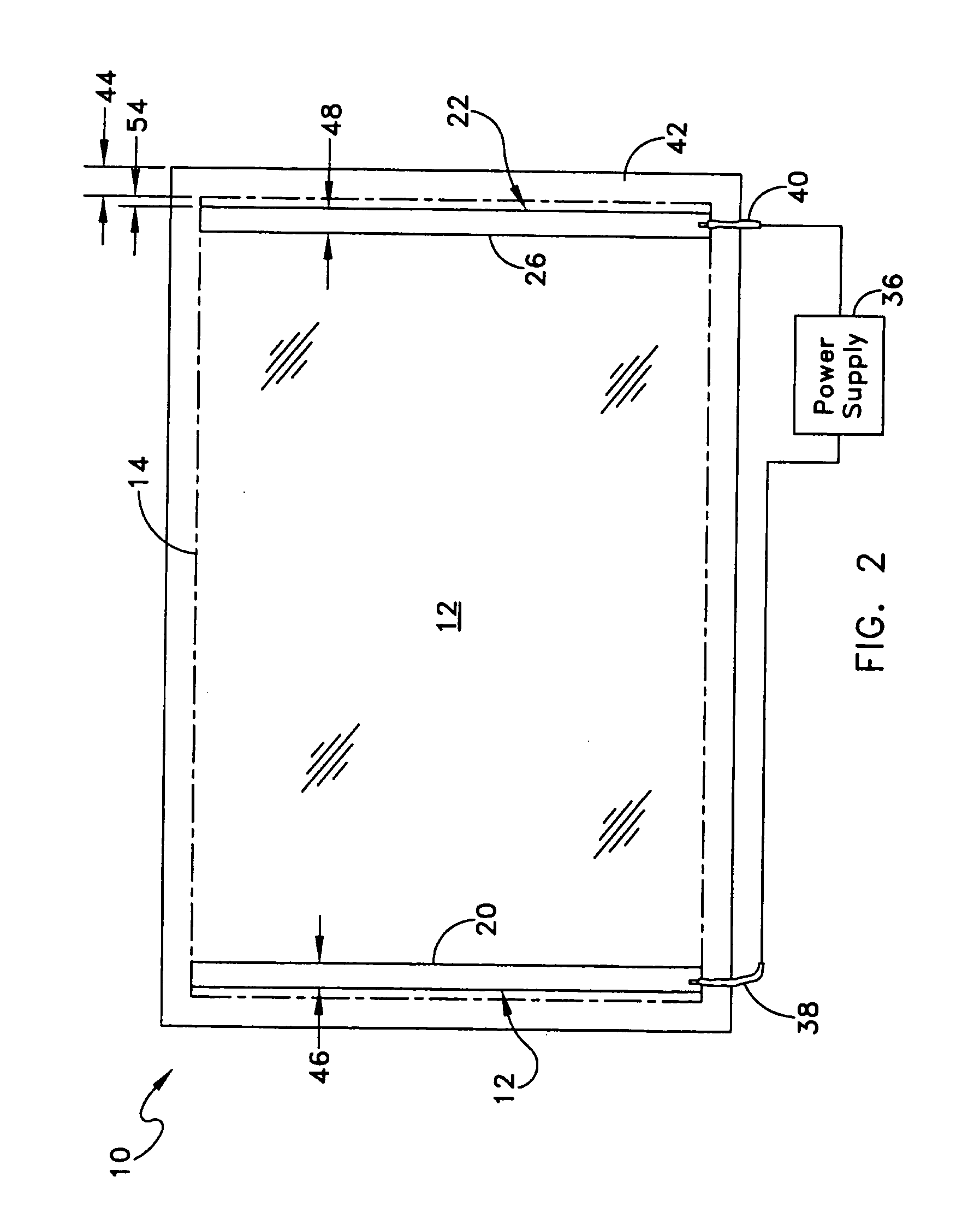
[0021] One embodiment of a heated glass panel 10 according to the teachings provided herein is best seen in FIGS. 1-3 and may comprise a first glass sheet 12 having an electro-conductive film 14 provided thereon. A first conductor 16 or bus bar is positioned at a first location 20 on the electro-conductive film 14. A second conductor 22 is positioned at a second location 26 on the electro-conductive film 14, as best seen in FIG. 2. A resilient material 28 is positioned on the first and second conductors 16 and 22. A second glass sheet 30 is positioned on the resilient material 28 in the manner best seen in FIG. 3, so that the resilient material 28 and conductors 16, 22 are sandwiched between the first and second glass sheets 12 and 30. The first and second glass sheets 12 and 30 are held together so that they exert a compressive pressure (illustrated by arrows 32) on the resilient material 28 and the first and second conductors 16 and 22, thereby holding the first and second conduct...


PUM


Abstract

A glass panel assembly according to one embodiment of the invention may include a first glass sheet having an electro-conductive film provided thereon and a conductor positioned at a location on the electro-conductive film. A retainer engages an edge portion of the first glass sheet and the conductor so that the retainer applies a compressive pressure to the conductor. The compressive pressure enhances electrical contact between the conductor and the electro-conductive film.

Description

CROSS-REFERENCE TO RELATED APPLICATION [0001] This is a continuation-in-part of co-pending U.S. patent application Ser. No. 11 / 352,005, filed on Feb. 10, 2006, which is hereby incorporated herein by reference for all that it discloses.TECHNICAL FIELD [0002] This invention generally relates to structures and methods for making electrical contact with electro-conductive films on substrates and more specifically to heated glass panels. BACKGROUND [0003] Heated glass panels are known in the art and are commonly used to reduce or prevent the formation of condensation or fog on the glass panels. For example, heated glass panels are commonly used in refrigerated merchandiser units of the type used in grocery stores to store and display refrigerated and frozen foods. Heated glass panels may also be used in other applications, such as bathroom mirrors and skylights, wherein it is desirable to reduce or eliminate the formation of condensation on the glass panels. Heated glass panels, typicall...

Claims


Application Information

Patent Timeline
IPC IPC(8): E06B3/00
CPCH05B3/84
Inventor BUSICK, STEVEFIGURELLI, GINO
Owner RADIANT GLASS INDS
Learn More