Fuel Cell System with Variable Coanda Amplifiers for Gas Recirculation and System Pressure Regulation

a technology of coanda amplifier and fuel cell, which is applied in the direction of fuel cells, exhaust gas recirculation, non-fuel substance addition to fuel, etc., can solve the problems that the proper functioning of the coanda flow amplifier cannot be guaranteed, and the mass flow of the drive, and thus the supply pressure of the drive fluid, will be affected by other system parameters, so as to achieve the effect of precise control of the mass flow ra

Inactive Publication Date: 2007-11-08
NUCELLSYS GMBH
View PDF4 Cites 43 Cited by
  • Summary
  • Abstract
  • Description
  • Claims
  • Application Information

AI Technical Summary

Benefits of technology

[0035] When using a Coanda flow amplifier in which the flow cross section of the drive-flow discharge slit can be variably adjusted, an appropriate choice of the flow cross section of the drive-flow discharge gap allows a very precise control of the mass flow rate of the anode gas to be supplied to the anode side of the fuel cell. Due to this, the Coanda flow amplifier additionally assumes a metering function to meter the anode gas volume, which is to be supplied to the anode side of the fuel cell and which is dependent on the load condition of the fuel cell.

Problems solved by technology

However, in some applications, and particularly for the use of a Coanda flow amplifier in a fuel cell system, one faces the problem that the mass flow of the drive fluid to be supplied to the Coanda flow amplifier, and thus the drive fluid's supply pressure, will also be affected by other system parameters.
Thus, under low-load conditions of the fuel cell one may be faced with the problem that the pre-set intake pressure of the drive fluid is not sufficient to accelerate the drive-fluid flow to a sufficiently high velocity when it passes through the drive-fluid discharge slit, so that the proper functioning of the Coanda flow amplifier can no longer be ensured.

Method used


Image

  • Fuel Cell System with Variable Coanda Amplifiers for Gas Recirculation and System Pressure Regulation
  • Fuel Cell System with Variable Coanda Amplifiers for Gas Recirculation and System Pressure Regulation
  • Fuel Cell System with Variable Coanda Amplifiers for Gas Recirculation and System Pressure Regulation

Examples


Embodiment Construction

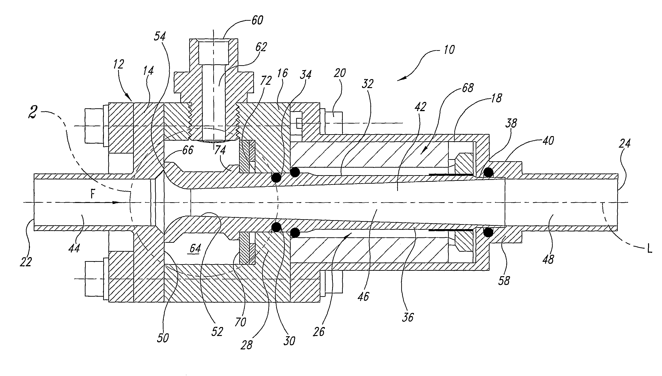
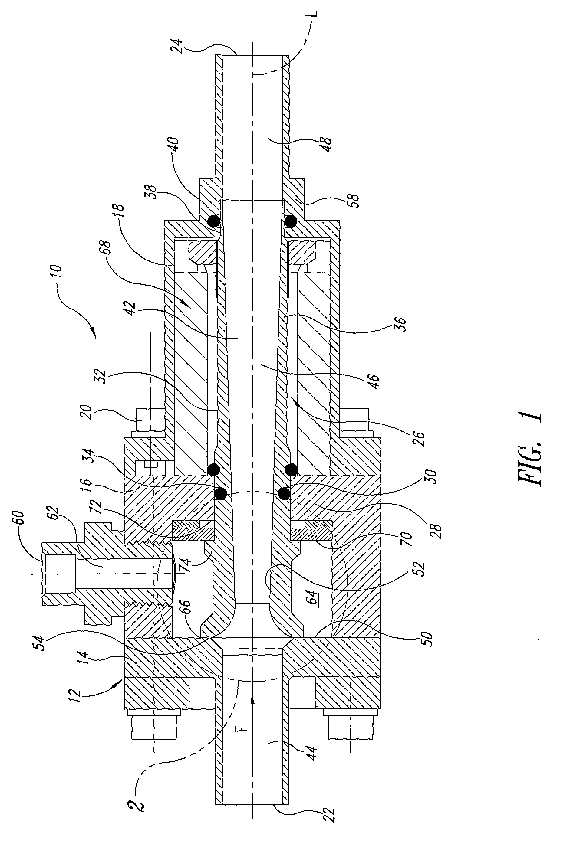
[0040] Referring to FIG. 1, a Coanda flow amplifier 10 is shown with a three-part housing 12, comprising a first housing section 14, a second housing section 16, and a third housing section 18. Each of the first, second, and third housing sections is executed as a separate component and the three components are rigidly connected to each other by a screw connection 20. The Coanda flow amplifier 10 is equipped with a suction intake 22 in the first housing section 14 and an outlet 24 in the third housing section 18.

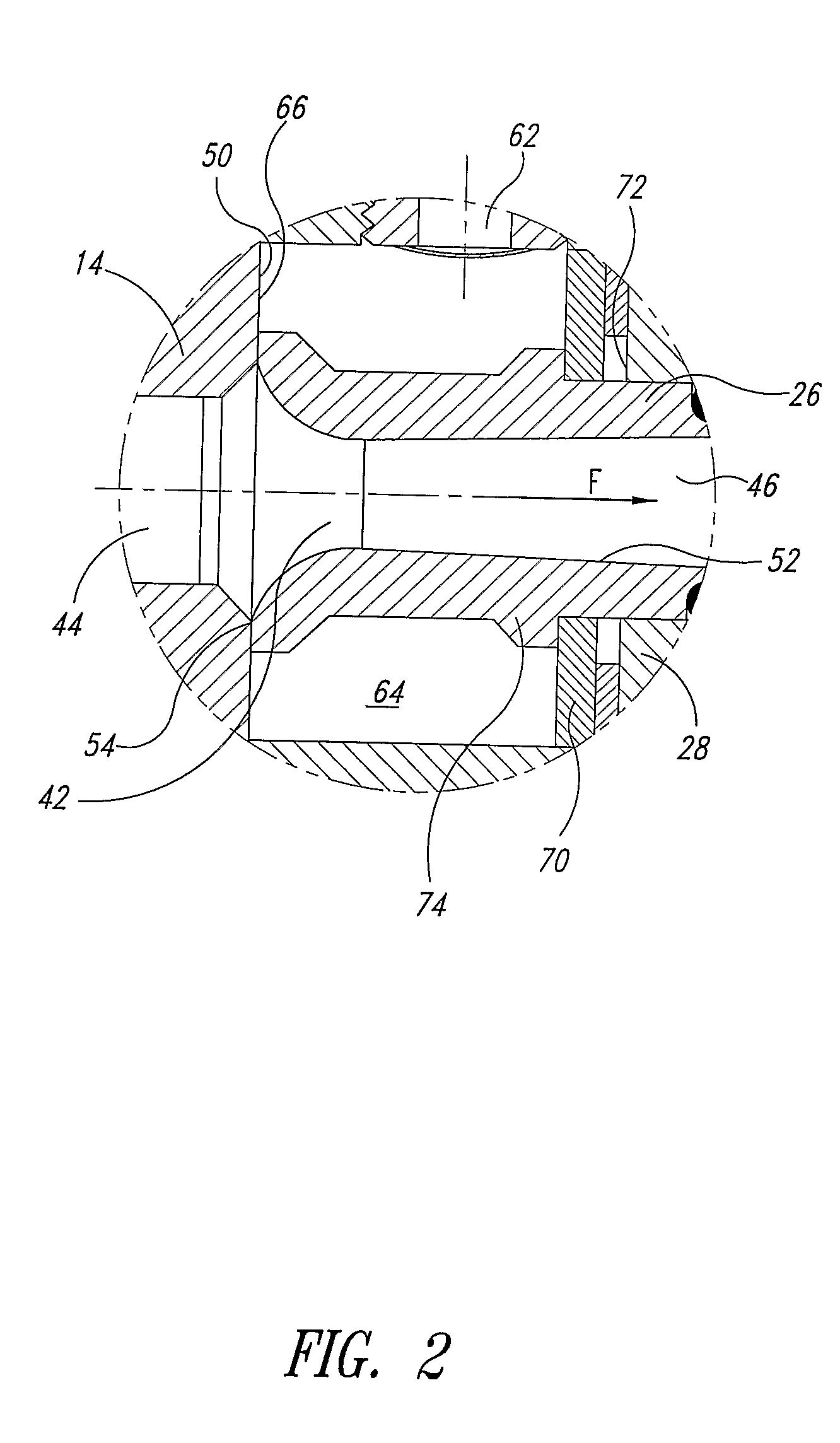
[0041] Arranged in the housing 12 is a flow-guiding element 26, which is guided in the housing 12 axially displaceable along a longitudinal axis L of the Coanda flow amplifier by a projection 28 of the second housing section 16 that protrudes radially inward, and which is sealed against the second housing section 16 by means of a first O-ring seal 30.

[0042] The first O-ring seal 30 is arranged in a groove 34 that is provided on an essentially cylindrical outer circumferenc...


PUM

PropertyMeasurementUnit
areaaaaaaaaaaa
axial displacementaaaaaaaaaa
pressure ratioaaaaaaaaaa

Abstract

A Coanda flow amplifier has a suction intake, an outlet, a fluid channel extending between the suction intake and the outlet, and a drive-flow inlet, which is fluidly connected to the fluid channel via a drive-flow discharge slit, whereby the flow cross section of the drive-flow discharge slit is variably adjustable. In a method to operate the Coanda flow amplifier, the variably adjustable flow cross section of the drive-flow discharge slit is chosen such that a pressure ratio between an output pressure of the drive flow when it leaves the drive-flow discharge slit, and an intake pressure of the drive flow when it enters the drive-flow discharge slit, does not exceed a critical pressure ratio. A fuel cell system comprises at least one fuel cell, a fluid source, a fluid line, and a Coanda flow amplifier arranged in the fluid line, whereby the Coanda flow amplifier is equipped with a drive-flow discharge slit with a variably adjustable flow cross section.

Description

BACKGROUND OF THE INVENTION [0001] 1. Field of the Invention [0002] The present application relates to a Coanda flow amplifier, comprising a suction intake, an outlet, a fluid channel extending between the suction intake and the outlet, and a drive flow inlet, which is fluid-connected to the fluid channel via a drive-flow discharge slit, as well as to a method of operating a Coanda flow amplifier of this type. The application further relates to a fuel cell system comprising at least one fuel cell, one fluid source, one fluid line, and one Coanda flow amplifier arranged in the fluid line, whereby both a suction intake and an outlet of the Coanda flow amplifier are fluid-connected to the fluid line, and whereby a drive flow inlet of the Coanda flow amplifier is fluid-connected to the fluid source. [0003] 2. Description of the Prior Art [0004] A Coanda flow amplifier of the above type is known in the art and has been described in, for example, U.S. Pat. No. 5,974,802. The operating pri...

Claims


Application Information

Patent Timeline
Patent Type & Authority Applications(United States)
IPC IPC(8): H01M8/04F15C1/06F02M25/07F04F5/18F04F5/52F04F5/54H01M8/02
CPCF02M25/0722F02M25/0739F04F5/18F04F5/54H01M8/04097H01M8/04201F15C1/08Y02T10/121H01M8/04089H01M8/04223H01M8/04231F15C1/003Y02E60/50F02M26/19F02M26/34H01M8/04225Y10T137/2224
Inventor SANG, JOCHENKNOOP, ANDREAS
Owner NUCELLSYS GMBH
Why Eureka
Try Eureka