
Bulk-Material Cooler for Cooling Hot Material to be Cooled

a technology of hot material and cooler, which is applied in the direction of furniture, lighting and heating equipment, transportation and packaging, etc., can solve the problems of reducing the service life of the grate cooler, affecting the thermal efficiency of such types of grate cooler, and being relatively expensive to seal off the cooling gra

Inactive Publication Date: 2007-11-08
KHD HUMBOLDT WEDAG GMBH
View PDF15 Cites 5 Cited by
  • Summary
  • Abstract
  • Description
  • Claims
  • Application Information

AI Technical Summary

Benefits of technology

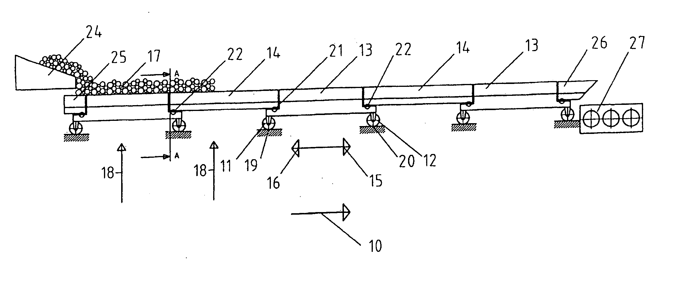
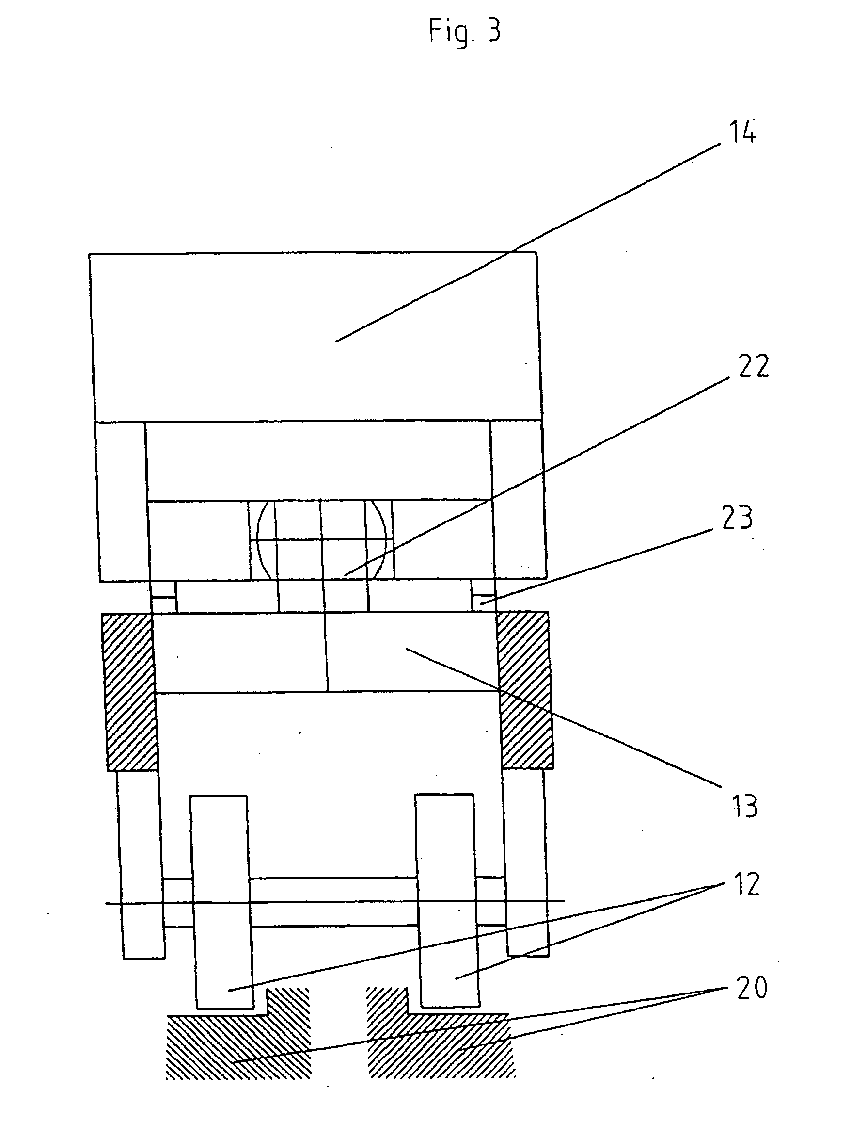
[0015] Owing to its low lateral guiding forces, however, the bulk material cooler according to the invention can also advantageously be used in applying compressive force to the longitudinal row of modules. A further advantage of the invention resides in the symmetrical construction of the modules. This ensures uniformity of the kinematics involved in the forward stroke and the return stroke. The lateral guiding forces are proportionally equal to the tensile and / or compressive forces. What can be said of the lateral guiding forces also applies to the vertical support forces. The relieving of the modules to a point where a bearing lifts off due to uneven vertical module loading, which would be possible in a railway wagon type of module, is precluded in a combination of carrier modules with hitched connecting modules. The force introduced into the driven modules from the approximately horizontal longitudinal feed force constitutes a further influence on the wheel loads. In order to protect the drive elements from fouling and wear, it is advisable to install the drive elements under the module conveyor tracks. The point of application of the force therefore lies significantly below the friction plane of the charged material to be cooled. This distance generates a moment, which leads to uneven loading of the axles of the module truck or carrier module. The long center-to-center distance reduces this effect. A further reduction in this effect is possible by inclining the direction in which the force is applied. This inclination in the direction of application of the force gives rise to a force component in a vertical direction, which achieves partial to complete compensation for the reduction in axle load.
resides in the symmetrical construction of the modules. This ensures uniformity of the kinematics involved in the forward stroke and the return stroke. The lateral guiding forces are proportionally equal to the tensile and / or compressive forces. What can be said of the lateral guiding forces also applies to the vertical support forces. The relieving of the modules to a point where a bearing lifts off due to uneven vertical module loading, which would be possible in a railway wagon type of module, is precluded in a combination of carrier modules with hitched connecting modules. The force introduced into the driven modules from the approximately horizontal longitudinal feed force constitutes a further influence on the wheel loads. In order to protect the drive elements from fouling and wear, it is advisable to install the drive elements under the module conveyor tracks. The point of application of the force therefore lies significantly below the friction plane of the charged material to be cooled. This distance generates a moment, which leads to uneven loading of the axles of the module truck or carrier module. The long center-to-center distance reduces this effect. A further reduction in this effect is possible by inclining the direction in which the force is applied. This inclination in the direction of application of the force gives rise to a force component in a vertical direction, which achieves partial to complete compensation for the reduction in axle load.

Problems solved by technology

In addition, in these known types of grate cooler the cross bar-shaped reciprocating elements are fixed on top of vertical drive plates oriented in the longitudinal direction of the cooler, which extend through corresponding longitudinal slots in the cooling grate and are driven from beneath the cooling grate, making it relatively expensive to seal off the cooling grate, charged with material to be cooled, to prevent material falling through the drive plate apertures, and thereby to keep the material wear within bounds.
The reciprocating elements moved in the hot cement clinker bed are exposed to a high level of thermal and mechanical wear, reducing the service life of the grate cooler.
Finally the hot bed of bulk material is intermixed by the reciprocating elements moved in the bed of material, which has a detrimental effect on the thermal efficiency of such types of grate cooler.
The actual floor elements remain uncooled by the cooling gas, so that the known cooling tunnel would be unsuited to cooling red hot cement clinker falling from the discharge end of a rotary kiln.
The direct contact of the hot cement clinker with the surface of the floor elements would mean exposure to a high level of thermal and mechanical wear and in the case of hot cement clinker would therefore lead to an inadequate service life of such a cooling tunnel.
Furthermore, the adjacent floor elements of such a cooler could not be used with a long length of 40 to 50 m, for example, such as industrial grate coolers need in terms of their throughput capacities and cooling line lengths for the cooling of hot cement clinker.

Method used


Image

  • Bulk-Material Cooler for Cooling Hot Material to be Cooled
  • Bulk-Material Cooler for Cooling Hot Material to be Cooled
  • Bulk-Material Cooler for Cooling Hot Material to be Cooled

Examples


Embodiment Construction

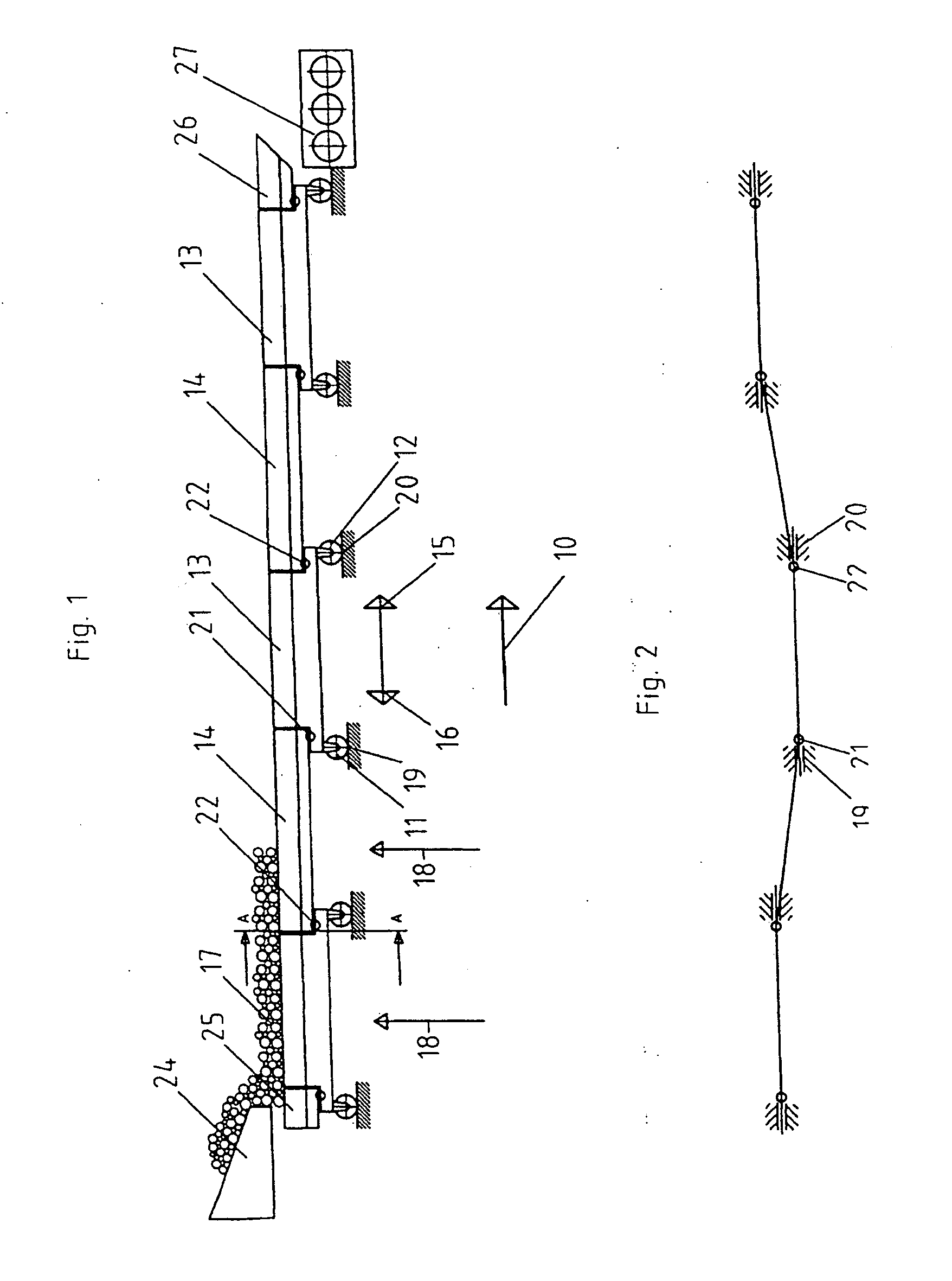
[0025] The bulk material cooler according to the invention will first be explained with reference to the exemplary embodiment in FIG. 1, in which the cooling grate, viewed over the length and over the width of the cooler, is assembled from multiple modules, the modules in each row arranged in series in the conveying direction 10 of the material to be cooled being coupled together. Each longitudinal row of cooling grate modules, of which one longitudinal row can be seen in FIG. 1, is assembled from carrier modules 13 supported bilaterally on support rollers 11, 12 alternating with connecting modules 14, the latter with no support rollers of their own being hitched onto the carrier modules 13.

[0026] The rows of cooling grate modules extending over the considerable length of the bulk material cooler are capable of controlled movement independently of one another between a forward stroke position 15 in the conveying direction of the material to be cooled and a return stroke position 16...


PUM

PropertyMeasurementUnit
Lengthaaaaaaaaaa
Widthaaaaaaaaaa
Areaaaaaaaaaaa

Abstract

The aim of the invention is to design a bulk-material cooler, particularly one for cooling cement clinker, which operates according to the walking floor principle, so that its cooling grate can be composed of a multitude of ventilated cooling grate modules, which can be assembled in an easy and variable manner, in order to obtain large lengths and widths of the cooler. When these cooling grate modules move between an advancing and returning position, even lateral and / or height offset of the guiding elements can be compensated for in a kinematic manner. To this end, the invention provides that the cooling grate, when viewed over the length and width of the cooler, is composed of a multitude of modules (13, 14) ventilated with cooling air. The coupling of the cooling grate modules of each longitudinal row of cooling grate modules is effected by an articulated joint.

Description

BACKGROUND OF THE INVENTION [0001] The invention relates to a bulk material cooler having a cooling grate which carries the material to be cooled, such as hot cement clinker, and which conveys the material to be cooled from the material charging end to the material discharging end while a flow of cooling gas flows through said material to be cooled. [0002] Grate coolers are used in the non-metallic minerals industry in order to drastically cool the material, such as cement clinker or other minerals, previously fired in a kiln, immediately afterwards on the cooling grate. For conveying the hot material to be cooled over the cooling line, the use of reciprocating grate coolers is particularly common, the grate system of which coolers comprises multiple alternately fixed and moving grate plate carriers, on each of which multiple grate plates are fixed, which are provided with cooling air apertures and which have a basically upward flow of cooling air passing through them. At the same t...

Claims


Application Information

Patent Timeline
IPC IPC(8): F27D15/02B65G25/06C04B7/47F27B7/38F27D19/00
CPCF27B7/38F27D15/0213F27D2015/0233F27D19/00F27D2015/0226F27D15/022
Inventor SPLINTER, CHRISTIANSCHINKE, KARL
Owner KHD HUMBOLDT WEDAG GMBH
Learn More