Image Processing Device And Method Which Use Two Images

a processing device and image technology, applied in the field of image processing devices and methods, can solve the problems of limiting the accuracy of matching, taking a long time to execute such a process, and the possibility of diagnostic form which was difficult in conventional diagnosis using silver salt photographs, so as to achieve the effect of reducing misregistration and high speed

Active Publication Date: 2007-11-08
CANON KK
View PDF15 Cites 41 Cited by
  • Summary
  • Abstract
  • Description
  • Claims
  • Application Information

AI Technical Summary

Benefits of technology

[0017] The present invention is completed to solve the above technical problems, and the object thereof is to provide image processing device and method which can generate a difference image at high speed as relatively decreasing misregistration, and a program which is used by a computer to achieve the above image processing method.

Problems solved by technology

Therefore, by digitizing a medical image, a possibility of diagnostic form which was difficult in conventional diagnosis using silver salt photograph comes out.
For this reason, there is a technical problem that it takes a long time to execute such a process.
Moreover, in the ROI matching, if plural similar patterns exist in the subject, there is a limit in accuracy of the matching.
Consequently, according to circumstances, it is impossible to avoid including a serious error in the shift vector.
In such a case, if the shift vector is interpolated by using the method of least squares, the included error influences other shift vectors, whereby displacement or misregistration occurs entirely.
For this reason, there is a technical problem that noise components increase in the difference image.
Besides, in a heart and a diaphragm, both the gradation information and the edge information are simple or poor.
Thus, for example, in the document 2, when the matching is executed by using the ROI of which the gradation information or the edge information is poor, it cannot necessarily be said that the matching of the ROI is accurately executed even if the weight of its shift vector is high, and it is impossible in this case to judge whether or not the information of the shift vector is correct.
For this reason, there is a technical problem that it negatively influences subsequent processes.

Method used


Image

  • Image Processing Device And Method Which Use Two Images
  • Image Processing Device And Method Which Use Two Images
  • Image Processing Device And Method Which Use Two Images

Examples


first embodiment

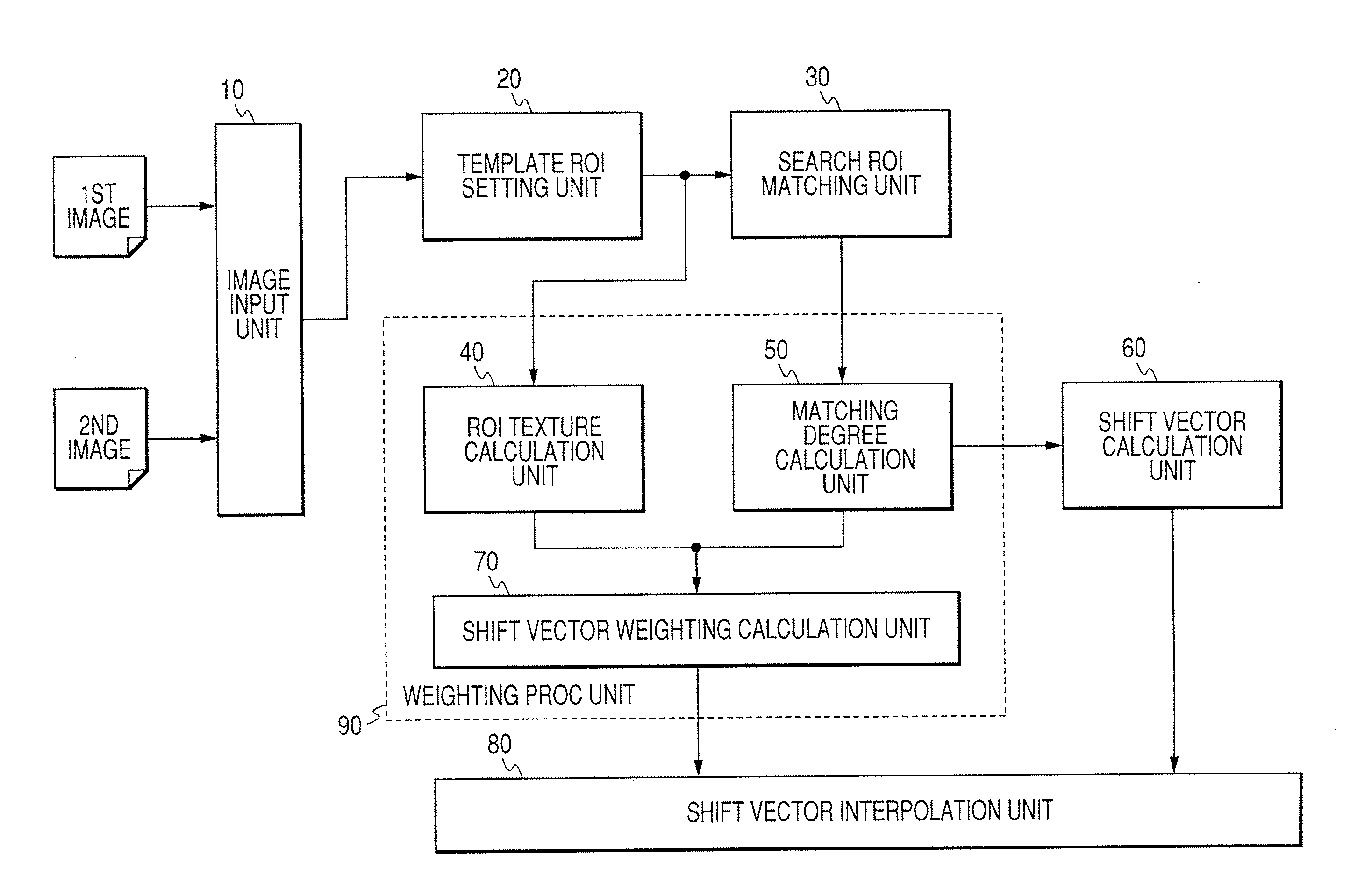
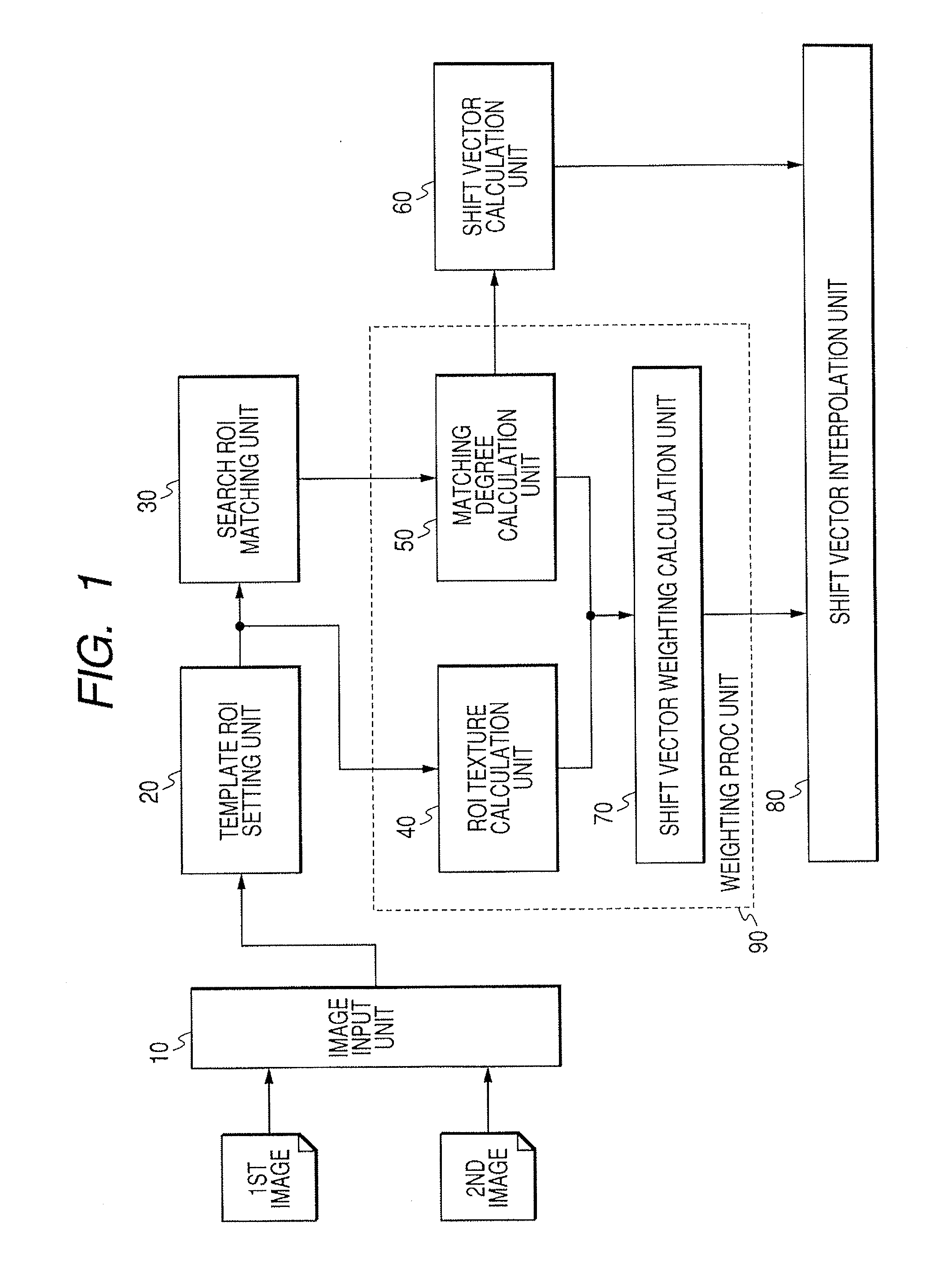
[0072] First of all, the first embodiment of the present invention will be explained hereinafter. FIG. 1 is a functional block diagram showing the functional constitution of a medical image processing device according to the first embodiment of the present invention. Incidentally, it should be noted that the medical image processing device according to the present embodiment may be achieved by a dedicated device for achieving the functions shown in FIG. 1 or by a control program for causing a general-purpose computer to execute the later-described processes. Moreover, it should be noted that it is possible to achieve each of the function blocks shown in FIG. 1 by hardware, software, or cooperation of hardware and software.

[0073] As shown in FIG. 1, the medical image processing device according to the present embodiment is equipped with an image input unit 10, a template ROI (region of interest) setting unit 20, a search ROI matching unit 30, an ROI texture calculation unit 40, a ma...

second embodiment

[0100] Subsequently, the second embodiment of the present invention will be explained hereinafter. In the second embodiment, it should be noted that the functional blocks are basically the same as those in the first embodiment, but only the function of the ROI texture calculation unit 40 is different from that in the first embodiment. FIG. 7 is a flow chart showing the operation of a medical image processing device according to the second embodiment of the present invention.

[0101] In the present embodiment, after the ROI was set with respect to the first image (step S103) as well as the first embodiment, an FFT (Fast Fourier Transform) coefficient is acquired by the equation (4) (step S201). F⁡(p,q)=∑m=0M-1⁢ ⁢∑n=0N-1⁢ ⁢I⁡(m,n)⁢ⅇ-j⁡(2⁢ ⁢π / M)⁢pm⁢ⅇ-j⁡(2⁢ ⁢π / N)⁢qn(4)

[0102] where p=0, 1, . . . , M-1, and q=0, 1, . . . , N-1

[0103] Here, the symbol M indicates the number of horizontal pixels of the template ROI, and the symbol N indicates the number of vertical pixel of the template ROI...

third embodiment

[0116] Subsequently, the third embodiment of the present invention will be explained hereinafter. In the third embodiment, it should be noted that the functional blocks are basically the same as those in the first embodiment, but only the function of the ROI texture calculation unit 40 is different from that in the first and second embodiments. FIG. 8 is a flow chart showing the operation of a medical image processing device according to the third embodiment of the present invention.

[0117] In the present embodiment, after the ROI was set with respect to the first image (step S103) as well as the first embodiment, a horizontal Sobel operator as indicated by the equation (8) is multiplied to the ROI, and thus horizontal edge intensity bx(i, j) of the image at the location (i, j) is calculated (step S301). Then, the horizontal Sobel operator as indicated by the equation (8) is multiplied to the ROI, and thus vertical edge intensity by(i, j) of the image at the location (i, j) is calcu...


PUM


Abstract

The present invention aims to provide image processing device and method capable of generating a difference image at high speed without occurring misregistration. To achieve this, in the image processing device and method, plural regions of interest are set respectively to input first and second images, a shift vector indicating a misregistration amount between the first and second images is calculated with respect to each of the regions of interest, a filter process is executed to the shift vector, the filter-processed shift vector is interpolated, the first and second images are registered based on the interpolated shift vector, and a subtraction operation is executed between corresponding pixels on the respective registered images to acquire the difference image.

Description

TECHNICAL FIELD [0001] The present invention relates to image processing device and method which are suitable for registration of two images being the target of a process such as a difference process or the like in CAD (computer aided diagnosis) technique or the like using medical images. BACKGROUND ART [0002] In recent years, use of digital images is advanced in the field of CAD. Therefore, by digitizing a medical image, a possibility of diagnostic form which was difficult in conventional diagnosis using silver salt photograph comes out. [0003] More specifically, in the conventional diagnosis, in a case where plural X-ray photographs which were taken at different points in time during observation of patient's condition are compared for diagnosis, the films on which the X-ray photographs have been respectively developed are generally hung on a light box (schaukasten), and the hung films are actually compared and read. [0004] Meanwhile, in the case where the digital images are used i...

Claims


Application Information

Patent Timeline
Patent Type & Authority Applications(United States)
IPC IPC(8): A61B5/00A61B6/00G06T1/00G06T5/50G06T7/00H04N5/325
CPCG06T5/50G06T7/003G06T2207/30061G06T2207/20224G06T2207/10116G06T7/337
Inventor SATO, MAKOTOGUO, MULING
Owner CANON KK
Why Eureka
Try Eureka